


13
Each unit must have an individual vent pipe and vent
terminal per furnace section!
Each unit MUST NOT be
connected to other vent systems or to a chimney.
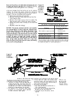
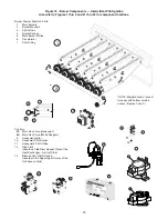
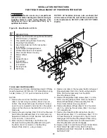
Units are shipped from the factory set up for vertical
venting. To convert the power venter for horizontal
venting, remove the shipping support bracket; refer to
Figures 10 and 24, and follow this procedure:
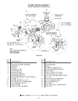
1. Hold power venter motor in position.
2. Remove the three Phillips-head screws from the
motor adaptor plate.
3. Remove the three screws which connect the
power venter stack to the power venter housing.
4. Rotate the power venter housing to the horizontal
position.
5. Replace screws accordingly.
NOTICE: The motor, pressure switch, and junction
box bracket MUST remain located as shipped from
the factory. Rotate only the blower housing! If the
power venter housing is to be moved to the right
horizontal position, the junction box must be rotated
90 degrees CCW to clear the connection. To do this,
remove all wires, conduit and conduit connector
from the junction box, noting location of wires. Move
box, using holes provided. Move 7/8" plug from
bottom of box to side. Reconnect all wires according
to the unit’s wiring diagram.
Figure 11
Adaptor
Installation
Figure 10
(Optional)
Top Vent
Position
Rear, Front,
Right & Left
Flue Positions
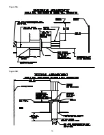
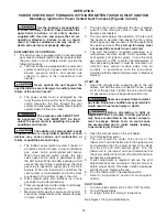
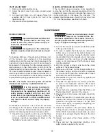
Vent Systems - Termination Clearance Requirements*
Minimum Clearances for
Structure
Termination Locations
4 feet below
Door, window or any gravity air inlet
4 feet horizontally
1 foot above
Forced air inlet within 10 ft.
3 feet above
Adjoining building or parapet
6 feet
Adjacent public walkways
7 feet above grade
*If the vent terminal is to be installed near ground level, the vent terminal
must be positioned at least six inches above the maximum anticipated
snow depth (see below for Canadian requirements)
REFER TO SPECIFICATION TABLE AND INSTALLATION MANUAL FOR PROPER USAGE
The following instructions apply to Canadian installations
in addition to installation and operating instructions:
1. Installation must conform with local building codes, or
in absence of local codes, with current CGA B149.1
installation codes for natural gas burning appliances
and equipment, or CGA B149.2, installation codes for
propane gas burning appliances and equipment.
2. Any references to U.S. standards or codes in these
instructions are to be ignored and the applicable
Canadian standards or codes applied.
3. If using a metal vent system under positive gauge
pressure in Canada, a slip fit vent connection must be
secured by at least two corrosion-resistant screws, or
other mechanical locking means.
4. The vent shall not terminate -
a. Less than 6 feet (1.8m) from a combustion air
inlet or another appliance.
b. Less than 3 feet (1m) from any other building
opening or any gas service regulator.
c. Directly above a gas utility meter or service
regulator.
* USA units - the
reducer must be
field supplied for
100, 125, 150 and
175 MBH unit sizes.
Summary of Contents for NATURAL INDOOR GAS-FIRED DUCT FURNACE
Page 14: ...14 Figure 12A Figure 12B...
Page 15: ...15 Figure 13A Figure 13B...
Page 34: ...34 NOTES...
Page 36: ......