


21
OPERATION
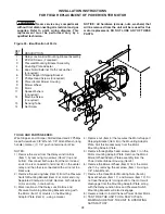
UNITS WITH INTERMITTENT PILOT IGNITION
Optional for Natural Vented (Standard) Duct Furnaces (Figures 1 and 2)
It is the installer’s responsibility
to check all safety controls! Check and test the
operational functions of all safety devices
supplied with this unit, and ensure that all are
operating effectively. Failure to do so could result
in unsafe conditions and may result in death,
serious injury or property damage.
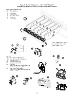
EXPLANATION OF CONTROLS (see Figure 19):
1.
The duct furnace is equipped with a dual automatic
gas valve and electric ignition device (separate from
the gas valve on some models) which provide the
following functions:
a.
Pilot solenoid valve is energized and pilot is
electrically ignited when thermostat calls for heat.
b.
Electronic circuitry proves that pilot flame is
established, then energizes main gas solenoid
valve.
c.
When thermostat is satisfied, main gas solenoid
valve and pilot solenoid valve are de-energized,
stopping all flow of gas.
d.
Pilot solenoid valve also functions as a main gas
valve to provide redundancy.
e.
Pressure regulator provides proper and steady
gas pressure to the main burners.
f.
Manual shutoff valve for service and long term
shut-down. (Separate from the automatic valve
on some models.)
2.
The high limit switch interrupts the flow of electric
current to the main gas valve in case the heater
becomes overheated.
3.
The optional fan switch delays the operation of the fan
until the heater is warmed, then keeps the fan running
after the gas has been turned off until the useful heat
has been removed.
The start-up fan delay must not
exceed 90 seconds from a cold start.
Make sure
your fan is functioning properly.
4.
The wall thermostat is a temperature sensitive switch
which turns the main gas valve ON or OFF to control
the temperature of the space being heated. It must be
mounted on a vibration free, vertical surface away
from air currents, in accordance with the instructions
furnished with the thermostat (also refer to Electrical
Section).
START-UP
1.
Open the manual valve supplying gas to the duct
furnace, and with the union connection loose,
purge air from the gas line. Tighten the union and
check for gas leaks, using a soapy water solution
only.
Never use an open flame to detect
gas leaks. Explosive conditions may exist which
would result in personal injury or death.
Before attempting to light or
relight pilot, wait 5 minutes to allow gas which
may have accumulated in the burner
compartment to escape. Failure to do so could
cause the accumulated gas to ignite rapidly,
leading to personal injury or death.
2.
Open the manual valve on the unit heater.
3.
Turn on electrical power.
4.
The unit should be under the control of the
thermostat. Turn the thermostat to the highest point
and determine that the pilot and main burners
ignite. Turn the thermostat to the lowest point and
determine that the pilot and main burners are
extinguished.
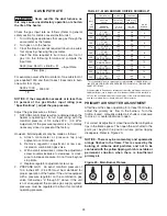
5.
If pilot adjustment is required, remove the pilot
adjustment seal cap and adjust the pilot screw to
obtain proper flame. Clockwise rotation decreases
pilot flame size. Replace the cap.
6.
Turn the thermostat to the desired position.
7.
Refer to “Adjustments” sections for more
specifications.
SHUT DOWN
1.
Turn the valve selector knob to the “OFF” position.
2.
Turn off the electricity.
3.
To relight, follow the “start-up” instructions.
See Figure 19 for parts/identification.
Summary of Contents for NATURAL INDOOR GAS-FIRED DUCT FURNACE
Page 14: ...14 Figure 12A Figure 12B...
Page 15: ...15 Figure 13A Figure 13B...
Page 34: ...34 NOTES...
Page 36: ......


