


10
ELECTRICAL CONNECTIONS
HAZARDOUS VOLTAGE!
DISCONNECT ALL ELECTRIC
POWER INCLUDING REMOTE
DISCONNECTS BEFORE
SERVICING. Failure to
disconnect power before
servicing can cause severe
personal injury or death.
Standard units are shipped for use on 115 volt, 60 hertz
single phase electric power. The motor name-plate and
electrical rating on the transformer should be checked
before energizing the duct furnace electrical system. All
external wiring must conform to the latest edition of ANSI/
NFPA No. 70, National Electrical Code and applicable
local codes; in Canada, to the Canadian Electrical Code,
Part 1 CSA Standard C22.1.
Do not use any tools (i.e. screwdriver,
pliers, etc.) across the terminals to check for power.
Use a voltmeter.
USE COPPER CONDUCTORS ONLY!
UNIT TERMINALS ARE NOT DESIGNED TO ACCEPT
OTHER TYPES OF CONDUCTORS. Failure to do so
may cause damage to the equipment.
It is recommended that the electrical power supply to each
duct furnace be provided by a separate, fused and
permanently live electrical circuit. A disconnect switch of
suitable electrical rating for each duct furnace should be
located as close to the gas valve and controls as possible.
Each duct furnace must be electrically grounded in
accordance with the latest edition of the National Electric
Code, ANSI/NFPA No. 70 or CSA Standard C22.1.
THERMOSTAT WIRING AND LOCATION
NOTICE: The thermostat must be mounted on a
vertical vibration-free surface free from air currents
and in accordance with the furnished instructions.
Mount the thermostat approximately 5 feet (1.5 m) above
the floor in an area where it will be exposed to a free
circulation of average temperature air. Always refer to the
thermostat instructions as well as our unit wiring diagram
and wire accordingly. Avoid mounting the thermostat in
the following locations:
1.
Cold areas - Outside walls or areas where drafts may
affect the operation of the control.
2.
Hot areas - Areas where the sun's rays, radiation, or
warm air currents may affect control operation.
3.
Dead areas - Areas where air cannot circulate freely,
such as behind doors or in corners.
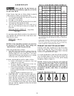
* Thermostat wires tagged “W” and “G” must be connected
together except when using a general purpose “SPDT”
24VAC relay and a standard thermostat with subbase, or
when using Honeywell T834H-1009 or T834H-1017
thermostats. Also refer to figure 8 for other wiring
connections.
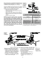
Figure 8 - C1267G
THERMOSTAT HEAT ANTICIPATOR ADJUSTMENTS:
The initial heat anticipator setpoint should equal the
heater control circuit's current (amperage) draw when
the unit is firing. This current should be measured for the
best results. Use the recommended ranges as a guide. If
further information is needed, consult your thermostat
manufacturer's instructions.
Recommended Heat Anticipator Setting Ranges:
25 ft. (7.6m)
50 ft. (15.2m)
Gas Ignition Type
T'stat Wiring
T'stat Wiring
For Natural Vent Units:
Standing Pilot
0.68 to 0.75 A
0.73 to 0.81 A
Intermittent (Spark)
0.76 to 0.81 A
0.81 to 0.91 A
For Power Vented Units:
Intermittent (Spark)
0.85 to 0.90 A
0.90 to 1.1 A
Max. Setting
on T'stat
FAN TIME DELAY CONTROL (OPTIONAL)
Leads from time delay controls are factory wired to the
junction box (when ordered as an optional component).
The fan control is a time delay relay (approximately 45
seconds ON, 65 seconds OFF). The fan control is rated at
17 amps.
NOTICE: The start-up fan delay must not exceed 90
seconds from a cold start.
NOTICE: For all wiring connections, refer to the
wiring diagram that your unit is equipped with (either
affixed to the side jacket or enclosed in your unit's
installation instruction envelope). Should any
original wire supplied with the heater have to be
replaced, it must be replaced with wiring material
having a temperature rating of at least 105
°
C.
Should any high limit or blocked vent (spill) switch
wires have to be replaced, they must be replaced
with wiring material having a temperature rating of
200
°
C minimum.
Summary of Contents for NATURAL INDOOR GAS-FIRED DUCT FURNACE
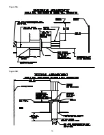
Page 14: ...14 Figure 12A Figure 12B...
Page 15: ...15 Figure 13A Figure 13B...
Page 34: ...34 NOTES...
Page 36: ......


