testing point to the cathode.
4.- The voltage value will appear on the LCD screen, in mVolts.
The meter will shows the dropped voltage in approximate
straight direction from the diode.
If the testing points are inverted, the meter will shows “1”
When a testing points is not connected, the meter will
display “1”.
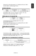
MEASURING AUDIBLE CONTINUITY
Warning
Make sure to discharge the capacitors and remove any kind of
energy, before to test continuity.
1.- Connect the red testing point in the jack signaled “
Ω
” and the
black testing point in the jack signaled “COM”.
2.- Set the dial to the “)))” range.
3.- Connect the testing points on the circuit to be measured. If
the resistance is less than 50 Ohms the multimeter will sound.
If the circuit is open, the screen will display “1”.
TRANSISTOR MEASUREMENT –hFE-
1.- Set the dial to the hFE range.
2.- Determine if the transistor is NPN or PNP and localize the
emitter, base, and collector. Connect the testing points in the
jacks for transistor testing.
3.- The multimeter will show the approximate hFE value.
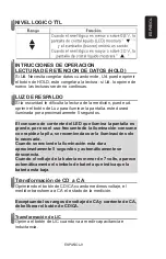
TTL LOGICAL TEST
1.- Connect the red testing point in the jack signaled “V” and the
black testing point in the jack signaled “COM”.
2.- Set the dial to the “ ” range.
3.- Connect the testing points on the circuit to be measured
4.- When the logical level is less than 0,8V the screen will display
“ “ and the meter will sound. When the logical level is over
than 2V, the screen will display “ “.
MAINTENANCE
BATTERY REPLACEMENT
Warning
Before removing the cover from your multimeter, make sure the
The meter will shows the dropped voltage in approximate
straight direction from the diode.
If the testing points are inverted, the meter will shows “1”
When a testing points is not connected, the meter will
display “1”.
ENGLISH
ENGLISH-12
If the circuit is open, the screen will display “1”.


