background image

Excepting the AC voltage range and AC current, you must 
release the DC / AC button.

L/C Switch

Press L/C button to measure capacitance and inductance.

MEASURING DC VOLTAGE

Warning

You cannot measure a voltage over 1000VDC, if you performs 
this action, the meter’s internal circuit will be damaged.

1.- Connect the red testing point to the jack signaled “V” and the 
black testing point to the jack signaled “COM”.
2.- Set the dial to the VDC / VAC setting 
3.- Connect the testing points to the equipment to be measured.
4.- Turn the equipment to be measured on, the voltage will 
appear on the LCD screen.  The polarity will also appear.
5.- When the value to be measured is unknown, set the dial to 
the maximum setting.

When a number “1” is displayed in the screen, it indicates 
that exists an over range, please select a higher range.

MEASURING AC VOLTAGE

Warning

You cannot measure a voltage over 700VAC, if you performs this 
action, the meter’s internal circuit will be damaged.

1.- Connect the red testing point to the jack signaled “V” and the 
black testing point to the jack signaled “COM”.
2.- Set the dial to the VAC / VDC setting.  Select the range. 
3.- Press D / AC button to change to AC measure mode.
4.- Turn the equipment to be measured on, the voltage will 
appear on the LCD screen.
5.- When the value to be measured is unknown, set the dial to 
the maximum setting.

When a number “1” is displayed in the screen, it indicates 
that exists an over range, please select a higher range.

Excepting the AC voltage range and AC current, you must 
release the DC / AC button.

When a number “1” is displayed in the screen, it indicates 
that exists an over range, please select a higher range.

When a number “1” is displayed in the screen, it indicates 
that exists an over range, please select a higher range.

ENGLISH

ENGLISH-9

Summary of Contents for MUL-400

Page 1: ......

Page 2: ...esistance capacity inductance diode or continuity on live circuits Whenever measuring voltages above 60 VDC or 30 VAC rms place your fingers above the protection rings on the testing points Never conn...

Page 3: ...e abrasive products or solvents DESCRIPTION 1 This multimeter is a portable professional digital instrument 2 4 digit LCD screen 25 mm tall with polarity indicator low battery indicator and hold butto...

Page 4: ...x 9 V alkaline or carbon zinc Maximum voltage between terminals and ground 1000 VCD or VCA Dimensions 185 x 84 x 38 mm Weight 441g including battery and case DC VOLTAGE Input impedance 10Mohm Protecti...

Page 5: ...t s very sensitive When the points touch the circuit the meter will shows the real reading DC CURRENT Protection against overcharge Ranges from 2 to 200mA F1 200mA fuse 200mA 250Vcc fast fusion 2ohm r...

Page 6: ...10 A connector 10A Voltage loss 200mA Frequency range 40 to 400Hz Response Average response calculated in rms sine wave RESISTANCE ohm Maximum voltage in open circuit 700mV Protection against overchar...

Page 7: ...fusion 2ohm resistance FREQUENCY Sensitivity 200mV rms and 10V rms maximum input Protection against overcharge 250V rms TRANSISTOR TEST Current base approximate 10 uA Vce approximate 2 8V Protection a...

Page 8: ...mes some energy because of the big screen if you use the light frequently the battery will discharged quickly we recommend to use the light only in specific cases The back light will be on for 5 secon...

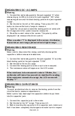
Page 9: ...ase select a higher range MEASURING AC VOLTAGE Warning You cannot measure a voltage over 700VAC if you performs this action the meter s internal circuit will be damaged 1 Connect the red testing point...

Page 10: ...COM 2 Set the dial to Ohms range 3 Connect the testing points to the circuit to be measured 4 The resistance value will appear on the LCD screen If the resistance to be measured is above 1 Mohm the mu...

Page 11: ...temperature value will appear on the LCD screen MEASURING FREQUENCY 1 Connect the red testing point to the jack signaled Hz and the black testing point to the jack signaled COM 2 Set the dial to 20KH...

Page 12: ...dial to the hFE range 2 Determine if the transistor is NPN or PNP and localize the emitter base and collector Connect the testing points in the jacks for transistor testing 3 The multimeter will show...

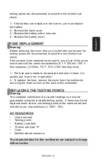
Page 13: ...1 The fuse rarely needs to be replaced and when it does it is usually due to an error in operation 2 To replace the fuse remove the cover from the multimeter removing the three screws on the back of...

Page 14: ......

Page 15: ...de rango a diferente escala o funci n desconecte las puntas de prueba del circuito Cuando lleve hacia fuera la medici n o interrumpa los circuitos de poder siempre recuerde que los pulsos de amplitud...

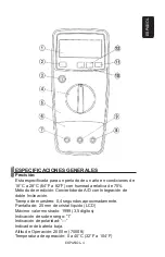
Page 16: ...la unidad 8 Para limpiar el mult metro utilice una trapo h medo y detergente suave no utilice abrasivos y o solventes DESCRIPCION 1 El mult metro es un instrumento Digital Profesional port til 2 Pant...

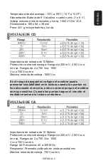
Page 17: ...de medici n Convertidor de A D con Integraci n de doble Inclinaci n Tiempo de muestreo 0 4 segundos aproximadamente Pantalla de 25 mm de cristal liquido LCD M ximo valor mostrado 1999 3 5 d gitos Indi...

Page 18: ...untas no han alcanzado el circuito esto es normal porque el medidor es muy sensitivo Cuando las puntas toquen el circuito el medidor mostrar la lectura verdadera VOLTAJE DE CA Impedancia de entrada de...

Page 19: ...nector de 10 A 10 A Ca da de voltaje 200mA CORRIENTE DE CA Protecci n contra sobrecarga Rangos 2 a 200 mA F1 fusible de 200 mA 250 V fusi n r pida resistencia 2 Ohms Rango de 10 A F2 fusible de 10 A 2...

Page 20: ...tecci n contra sobrecarga F1 fusible de 200 mA 250 V fusi n r pida resistencia 2 Ohms Rango de 10 A F2 fusible de 10 A 250 V fusi n r pida INDUCTANCIA Protecci n contra sobrecarga F1 fusible de 200 mA...

Page 21: ...e 10 uA Vce aproximadamente 2 8 V Protecci n contra sobrecarga F1 fusible de 200 mA 250 V fusi n r pida resistencia 2 Ohms PRUEBA DE DIODOS Corriente de prueba en sentido directo 1 mA aproximadamente...

Page 22: ...es menor de 7 volts aparece autom ticamente el s mbolo de bater a que indica que la bater a esta baja Transformaci n de CD a CA Oprimiendo el bot n de CD CA cuando medimos voltaje el medidor transform...

Page 23: ...Advertencia Ud no puede medir un voltaje arriba de 700 VCA si lo hace destruir el circuito interno del medidor 1 Conecte la punta de prueba roja al conector hembra Jack marcado como V la punta negra a...

Page 24: ...ntas roja en y negra en COM 2 Coloque el selector giratorio en la escala de Ohms 3 Conecte la puntas de prueba al circuito a medir 4 Lea el valor de resistencia en la pantalla display digital 1 Para r...

Page 25: ...no conecte el termopar en circuitos con energ a 1 Coloque el selector en la funci n de C 2 La pantalla de cristal l quido LCD mostrar la temperatura ambiente 3 Inserte el termopar tipo K dentro del co...

Page 26: ...ador buzzer sonar Si el circuito esta abierto la pantalla mostrar 1 MEDICION DE TRANSISTOR hFE 1 Coloque el selector en la posici n de hFE 2 Determine si el transistor es de tipo NPN o PNP y localice...

Page 27: ...de reemplazar el fusible Para proteger de un riesgo de incendio reemplace los fusibles solo con id nticos a los originales F1 F 200 mA 250 V de respuesta r pida 2 Ohms F2 F 10 A 250 V de respuesta r...

Page 28: ...ueba Bater a de Cortes a Termopar tipo K Funda Conector multifunci n El dise o del producto y las especificaciones pueden cambiar sin previo aviso El dise o del producto y las especificaciones pueden...

Page 29: ...es to costumer as well as warranty service at any of the addresses mentioned later THIS WARRANTY IS VOID IN THE NEXT CASES If the product has been damaged by an accident acts of God mishandling leaky...

Page 30: ...EFECTIVA EN LOS SIGUIENTES CASOS 1 Cuando el producto ha sido utilizado en condiciones distintas a las normales 2 Cuando el producto no ha sido operado de acuerdo con el instructivo de uso 3 Cuando e...

Reviews: