background image

Getting Started: PLEASE READ ENTIRE CONTENTS OF THE MANUAL BEFORE OPERATION 


Powering On/Off: 

1.


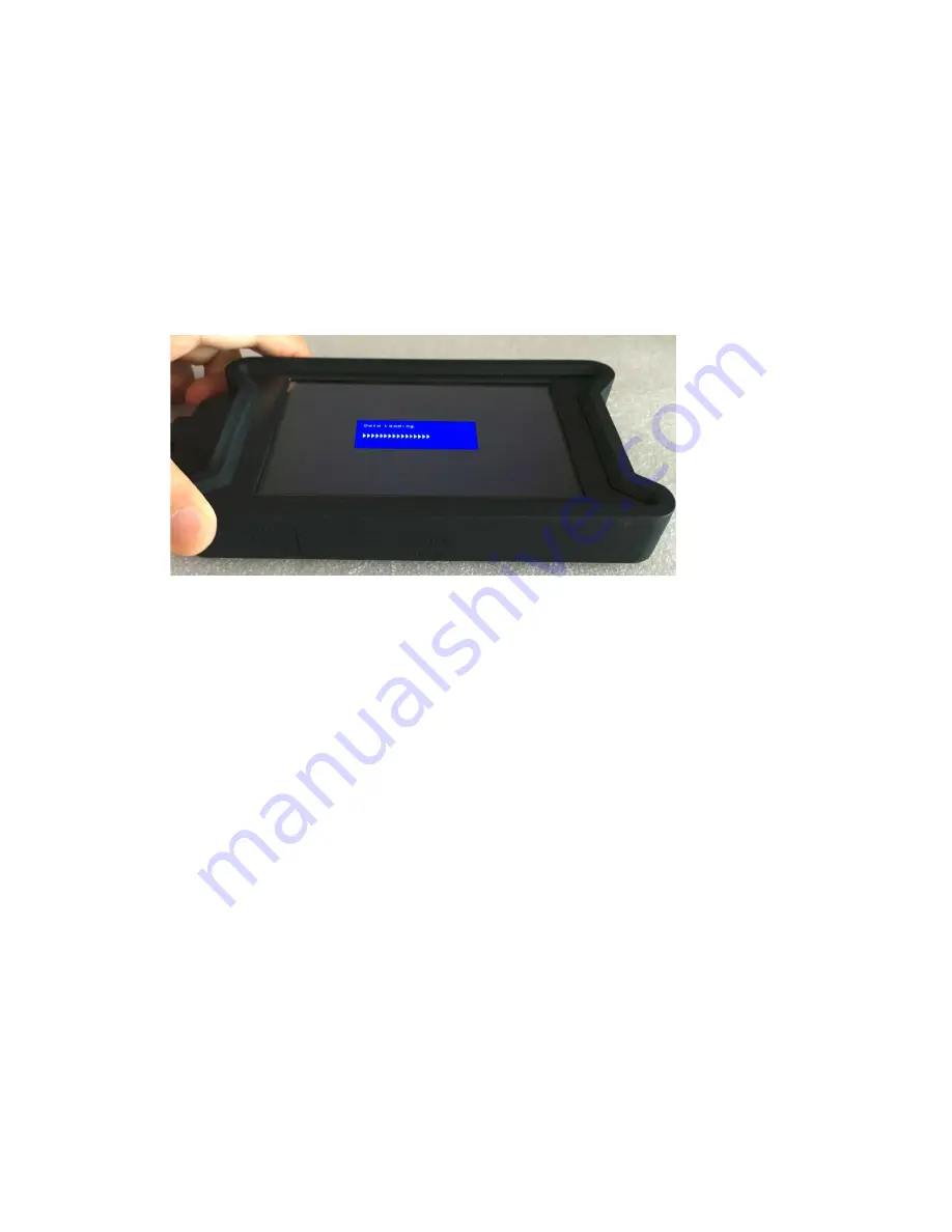
To power on the unit, press and hold the ① “Power” button for 3 seconds until the pop-up 
menu shown below appears (Fig 1). 

2.


To power off the unit, press and hold the ① “Power” for 3 seconds and release.


(Fig 1) 


Changing Input Modes:  


1.


Press ② 

Input

 to toggle between “HDMI Test Input” and “HDMI Display Input” 

2.


Selecting the HDMI Test Input will display the 19 Pin Test screen 

3.


Selecting the HDMI Display Input will display a video signal when present 

4.


The ② 

Input 

is the primary function button to conduct both test features 


Menu and Settings Navigation:  


1.


To access the device menu, press the 

③ Menu

 button.  

2.


To navigate the menu use the ④ “ 

− “

 button to navigate down on the menu and use the ⑤    


“ + ” to navigate up on the menu 

3.


Once in the menu, use the 

③ Menu

 button to select the highlighted option 

4.


To go back in the menu, use the ⑥ 

Back 

button to go back one step.


Summary of Contents for BL-526-105

Page 1: ...ngs Menu Menu navigation Down Menu navigation Up Back Returns to the previous menu Speaker Audio output fixed Test Input A To be used in HDMI Test Input mode for cable testing Test Input B To be used...

Page 2: ...d HDMI Display Input 2 Selecting the HDMI Test Input will display the 19 Pin Test screen 3 Selecting the HDMI Display Input will display a video signal when present 4 The Input is the primary function...

Page 3: ...nly available while on the HDMI Display Mode The OSD on screen display menu allows for manual adjustments of the parameters as seen below It is recommended to keep the values set to the default values...

Page 4: ...ne of the two available testing modes a HDMI Test Input Used for testing an HDMI Cable For HDMI Test Input Mode plug one end of the HDMI cable you need to test into Test Input A port and the other end...

Page 5: ...ines display as green which is a full passing result Fig 5 Fig 5 2 If the HDMI cable is not correctly hooked up to both test inputs all 19 lines will be shown as RED Fig 6 Fig 6 3 In some cases an HDM...

Page 6: ...f each of the HDMI pins Abbreviations have been added for each pin on the HDMI Display Tester for reference Please reference the table below Pin Description Abbv Pin Description Abbv Pin 1 TDMS Data2...

Page 7: ...he source image or play sound please check that the source device is powered on set for playback and set for HDMI video audio output Input Resolution Test 1 Follow the Source Display Testing section s...

Page 8: ...Year Warranty which warrants only to the original purchaser of this product from a Steren authorized reseller or distributor that this product will be free from defects in material and workmanship und...

Reviews: