Stentorfield Contour Operator'S Manual Download Page 15

13

Operator’s Manual

1.

On arrival at the machine, open the door. Fill a
cleaning bucket with hot water and dilute the
bactericidal cleaner in accordance with the
instructions on the product packaging.

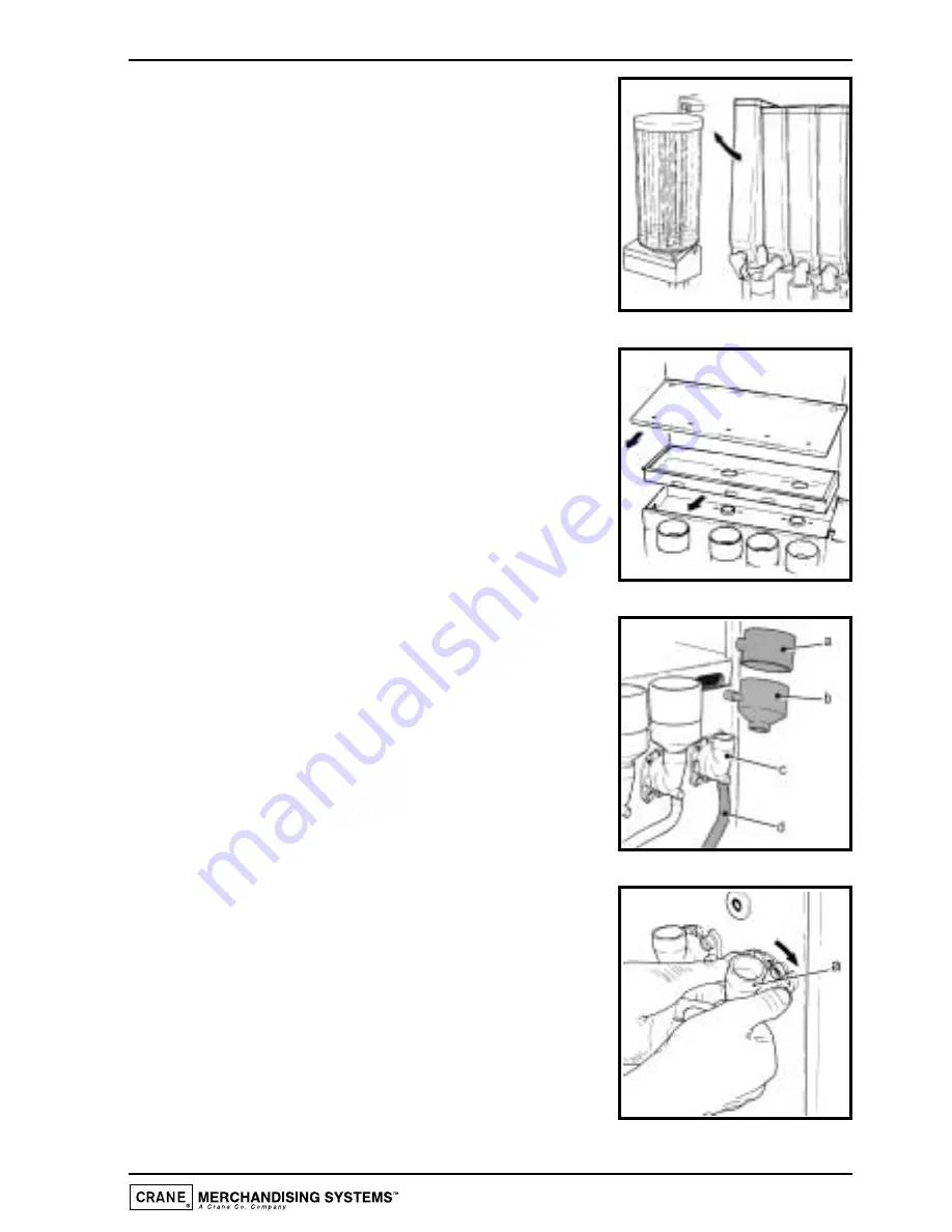
Swing the cup turret assembly out of the machine
in order to gain access to the ingredient canisters.

Remove the ingredient canisters. DO NOT PLACE
THEM ON THE FLOOR.

2.

Remove the canister shelf and extract tray.

Using a dry brush, clean the area under the extract
tray.

Wipe the upper interior of the machine. Clean the
extract tray and refit into machine.

3.

Remove steam hoods (a) and mixing bowls (b) from
whipper bases (c).

Remove the dispense pipes (d) from the whipper
bases (c) and the plastic dispense block.

Remove the plastic thumb-screw securing the
plastic 

dispense 

block

to the dispense head

assembly. Remove the dispense block and clean
thoroughly with the mixing system components.

4.

Remove the complete whipper unit (a), including the
whipper base as shown.

Split the whipper unit into separate parts - whipper
base, mixing chamber and impeller.

Clean all of the mixing parts, including the steam
hoods and mixing bowls thoroughly in the diluted
bactericidal cleaner solution.

Rinse all components with clean water and dry
thoroughly before refitting to machine.

Summary of Contents for Contour

Page 1: ...O P E R A T O R S M A N U A L Part No PR09682000 Issue 2 02 02 Profile Contour Profile Contour O P E R A T O R S M A N U A L ...

Page 2: ......

Page 3: ...Supply 8 Setting Up 9 How to Vend a Drink 11 Daily Cleaning and Re filling 12 Coffee Brewer Maintenance 17 Tea Pot Brewer Cleaning 18 Operator Functions 19 Problem Solving 30 De commissioning the Machine 31 Recommended Spares List 32 The following symbol is used throughout this Operator s Manual Safety First Take care risk of personal injury Copyright 2002 Crane Merchandising Systems 1 Operator s ...

Page 4: ... not likely to be knocked off 3 The mains lead should never trail from the machine and should always be kept away from hot surfaces and sharp edges 4 Do not operate the machine if any part is damaged e g mains lead until it has been checked by a qualified Service Technician 5 Allow the machine to cool before handling or moving 6 Never immerse the machine in water or any other liquid and never clea...

Page 5: ...ensuring complete reliability and flexibility Up to twelve independent drink prices are available Alternative prices and free vend periods are available on all selections Full cost control is maintained via the audit facility This provides precise information on drink counts and ingredients used It is the policy of Crane Merchandising Systems to continue developing its range of beverage equipment ...

Page 6: ...ould be replaced every six months or earlier depending upon the number of vends 4 Operator s Manual Profile Contour Height 985 mm 985 mm Depth 590 mm 590 mm Width 540 mm 660 mm Weight 105 kg 184 kg Electrical Services i Voltage 220 240 Volts AC ii Current 13 Amp Fused iii Frequency 50 Hz Water Services i Pressure 100 Kpa 1 Bar 800 Kpa 8 Bar ii Stopcock 15 mm BSP from rising main Cup Capacity 350 w...

Page 7: ...s Note Illustration shows the Contour Key 5 Operator s Manual 1 2 3 4 5 6 7 8 9 1 Door 2 Door Lock 3 Cup Stand 4 Drip Tray 5 Selection Decals 6 Coin Entry where fitted 7 LCD Display 8 Keypad 9 Coin Return where fitted ...

Page 8: ...eshbrew machines only 2 Coffee Brewer Freshbrew machines only 3 Tea Brewer Freshbrew Contour machines only 4 Large Freshbrew Waste Bucket 5 Small Freshbrew Waste Bucket 6 Drip Tray Grill 7 Mixing System 8 Cup Turret 9 Large Ingredient Canister 10 Door Switch 11 Filter Paper Roll Freshbrew machines only 12 Small Ingredient Canister ...

Page 9: ... is sufficient access space available via passageways stairs lifts etc and that the table counter where the machine is to be located is strong enough to safely support its weight Refer to Specifications Table 6 The machine should be located near the appropriate water and electrical services as detailed in the specification table 7 To ensure adequate ventilation 100 150 mm 4 6 inches clearance must...

Page 10: ...ystem via the stop tap several gallons before connecting the hose to the machine 4 Connect the hose to the inlet valve located on the rear of the machine Ensure that the seal is correctly fitted Ensure that all water supply fittings are tight Turn on the stop tap and check for leaks Connecting the Electricity Supply Safety First THE MACHINE MUST BE EARTHED ON NO ACCOUNT SHOULD IT BE EARTHED TO THE...

Page 11: ...ray Check the system for leaks Safety First Should the machine fail to fill correctly or leak turn off the stopcock and contact the machine supplier for assistance 6 Check the LCD display on the front of the machine to ensure that the water has heated to the correct temperature and that the machine is in standby mode The display will show the message Where XX XX is the current time 7 Loading the c...

Page 12: ...osition remove the safety key from the door switch to switch off the power to the machine Remove the brewer cover Carefully feed the filter paper under the raised chamber and through the feed wheels Refit the brewer cover Replace the safety key into the door switch to restore power to the machine The filter paper will index automatically and the brewer chamber will return to the closed position Wh...

Page 13: ...ivered into the cup 3 The dispense head returns to its parked position and the display will tell you when your drink is ready Remove the cup carefully from the cup catcher Press the coin return button situated next to the coin entry to receive any change owed 4 To vend a drink into your own cup lower the cup stand to horizontal position Place your cup on the stand Select a drink as described above...

Page 14: ...wder agent which should be dissolved in clean water in accordance with the instructions on the product packaging The solution can be used on heavily soiled or stained components such as buckets and drip trays Items or surfaces cleaned with this solution must be rinsed in clean water to remove traces of the cleaning agent Liquid Destainer Brewer Units Crane Merchandising Systems recommends that a l...

Page 15: ...ray and refit into machine 3 Remove steam hoods a and mixing bowls b from whipper bases c Remove the dispense pipes d from the whipper bases c and the plastic dispense block Remove the plastic thumb screw securing the plastic dispense block to the dispense head assembly Remove the dispense block and clean thoroughly with the mixing system components 4 Remove the complete whipper unit a including t...

Page 16: ... that the dispense pipes are located into their correct positions in the dispense block as shown in the illustration 7 With a damp sanitised cloth remove any ingredient on the exterior of the canisters including any product build up around the canister outlets Check ingredient canisters and refill if required Refit the canisters into the machine from left to right Ensure that the canisters are ref...

Page 17: ...e ensuring that drain pipe is correctly located through drain hole 11 Check the levels of the cups in the cup stack Where necessary remove the cup stack lid and fill Important Do not fill the tube directly above the cup dispense position Allow the cup turret to rotate a full tube to the cup dispense position Rotating the cup turret by hand will damage the mechanism DO NOT TOUCH THE CUPS WITH YOUR ...

Page 18: ...itch located in the switch panel on the rear of the door and enter the correct operator code selection button 1 followed by 7 Proceed as follows i Press the flush switch and check that all of the mixing stations are water tight ii Using the service switch test vend each drink selection iii Press the view counters switch and record the audit information Remove the safety key and close the door Clea...

Page 19: ...cating bracket Thoroughly clean the external surfaces of the brewer 8 With the brewer unit removed from the machine clean the area surrounding its locating bracket Refit brewer to machine and refit the outlet pipe to the dispense head 9 Switch on the power using the door switch safety key The brewer chamber will return to its closed position 10 Pour 2 3 full cap measures of de staining fluid direc...

Page 20: ...assembly and mounting bracket using the liquid destaining agent Follow the instructions for soak cleaning on the product packaging Rinse all components with clean water and dry thoroughly 2 Undo the thumb screw retaining the brewer unit Remove the complete brewer unit from the machine as shown 3 Split the brewer unit into its separate parts as shown Clean bowl a gauze b and outlet c using the liqu...

Page 21: ...s defined in Figure 1 in order to enter values and commands Figure 1 During programming the keys are used as follows Buttons 0 9 Used for entering data C Used for correcting data Blank For moving to a higher programme level Strong For indexing up in a programme or incrementing data Mild For indexing down in a programme or entering data Normal For entering data in a programme or moving to a lower p...

Page 22: ... down keys 4 To access a displayed sub program press the access normal key 5 If any numerical data parameter is entered it may be changed in one of two ways a Pressing the up or down keys increases or decreases the number on each key press b Keying in the actual digits of the number required Using this method the new number will be displayed in place of the current parameter 6 Once the correct num...

Page 23: ...atically and the brewer chamber will return to its closed position Flush Switch 1 The Flush sequence operates automatically and flushes the complete water system Before the sequence begins the system waits until the water is at the correct temperature determined by the thermostat During the entire sequence the LCD displays the message 2 In order to guarantee the highest standards of cleanliness th...

Page 24: ... that the waste tray is empty and in place and keep hands away from the dispensing area whilst the flushing cycle is in operation a Open the front door of the machine and insert the safety key b Press and release the brewer flush switch c Empty the waste tray when complete View Counters Switch 1 Internal counters monitor the numbers of vends of each drink type the number of jug vends free vends an...

Page 25: ...rogram pressing the access key on the keypad will display the Service function Pressing the access key again will carry out the function described To move to the next function press the up or down keys To return to the main menu press the cancel C key The operations sub program is split into seven separate functions a Service When accessed this function allows the operator to test vend each drink ...

Page 26: ...nto the cup catcher This ensures that the mechanism is working correctly g Park Head Pressing the access key on the keypad causes the dispense head to move to its fully extended dispensing position Press the key again to return the head to its parked position Note The service self clean paper feed and brewer flush functions duplicate the functions of the service flush paper feed and brewer flush s...

Page 27: ...alternative tariff 1 sub program except that the prices set here will be in force during tariff 2 periods Alternative Price Period Sub Program This sub program enables the times to be specified when each of the above tariffs should be in force There is a four level tariff structure available 1 Normal Tariff This relates to prices set in the drink price sub program and in force when no alternative ...

Page 28: ... the day setting between Every day Weekdays and Weekends When the required day setting is displayed press the access key to complete the price period data entry The message on the display will read 7 There are a maximum of ten possible price periods available To enter another price period use the up or down keys to view the periods until an empty period is displayed The new period is entered in th...

Page 29: ... program with the LCD displaying the weights of individual ingredients used Weights are displayed in units of one kilogram 2 There is one weight counter displayed for each ingredient allocated to a canister in the canister configuration sub program These counters are reset using the using the reset counters function within the operations sub program Time Date Sub Program The machine maintains a re...

Page 30: ...ate is now set To view the day press the up or down key until the display reads where xxxxxxxxx is the current day of the week 9 To change the day press the access key The display will now show 10 Use the up or down arrow keys until the required day is displayed Press the access key The time date and day are now programmed Operator Code Sub Program Default 17 Entry into the Operator code sub progr...

Page 31: ...ntered correctly via the keypad followed by a two digit drink selection number allows a jug to be vended Entry into the jug code sub program allows the operator to set a unique jug code 2 Access the jug code and enter a new code using buttons 0 9 on the keypad Press access to overwrite the old code ...

Page 32: ...ng from dispense Mixing bowls chambers Refit correctly and ensure area fitted incorrectly that all mixing stations are water tight Low water showing Water supply Ensure water supply is on LCD display turned off turned on at stop tap Blank LCD display Electricity supply Ensure electricity supply turned off is turned on at the mains Cups jamming Incorrect cup size Remove cups from cup turret and rep...

Page 33: ...ds for example over a long weekend no special treatment is required The machine should be thoroughly cleaned before the site is closed down and on return it is advisable to vend each drink type to ensure correct operation and to freshen up the machine If the machine is to be moved or transported remove all ingredients and thoroughly clean the machine If a coin module is fitted remove any cash from...

Page 34: ...70000 Impeller 5 i PL02275000 Mixing Chamber Grey ii PL02495000 Mixing Chamber Black 6 SI01171960 Silicon Pipe 7 i PL01967000 Mixing Bowl Grey ii PL02458000 Mixing Bowl Black 8 i PL01966000 Steam Trap Grey ii PL02457000 Steam Trap Black 9 PL01313000 Canister Tall 10 WF01176000 Filter Paper Roll 11 ME01849000 Retaining Clip 12 PL02266000 Canister Short 13 PL04407000 Canister Lid Rectangular 14 PL02...

Page 35: ...ption 15 i PL01795000 Freshbrew Coffee Canister Square ii PL04607000 Freshbrew Tea Canister Square 16 i PL01128000 Canister Chute ii PL01441000 Canister Chute LH iii PL01442000 Canister Chute RH 17 MT05429000 Drip Tray Grill 18 PL05189000 Drip Tray ...

Page 36: ...Notes 34 Operator s Manual ...

Page 37: ...Notes 35 Operator s Manual ...

Page 38: ...Notes 36 Operator s Manual ...

Page 39: ......

Page 40: ...Pipsmore Park Bumpers Farm Industrial Estate Chippenham Wiltshire SN14 6NQ Tel 44 0 1249 444807 Fax 44 0 1249 444819 Email sales cranems co uk Website www cranems co uk ...

Reviews: