6.7. Layout
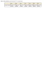
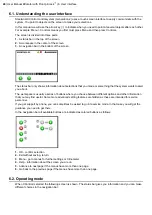
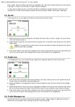
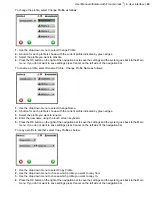
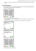
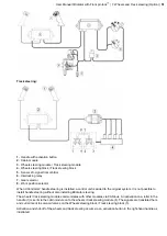
In the layout menu, you can get information about the buttons and rollers on your joysticks are configured.
The indications on the screens are as follows:
•
R1-R4: shows symbols for rollers where R1 = left thumb roller, R2 = left index finger roller, R3 = right thumb
roller and R4 = right index finger roller
•
1-14: shows symbol for buttons according to diagram above where buttons 1-4 and 8-11 are on the joystick's
thumb side (i.e. towards the driver) whilst buttons 5-7 and 12-14 are on the joystick's index finger side (i.e. away
from the driver)
•
R1+7: shows that a function is controlled by simultaneously using button #7 and activating S1 roller.
Change the layout for left and right handles by pressing the arrow buttons in the navigation bar.
To return to a higher level press Cancel on the left side of the navigation bar.
6.8. Clinometer
The clinometer is a useful tool that indicates how your work tools are oriented. The clinometer shows the tilt angle,
the bucket and rotation angle of your work tool.
The tilt angle is displayed by the indicator tilting from right to left.
The bucket angle is displayed by the indicator moving up or down.
The angle of rotation is indicated by the rotation point indicator moving around the perimeter of the clinometer.
A desired reference point can be set as follows:
1.
Press the Set button to indicate a reference position.
44
| User Manual tiltrotator with Front pin lock
™
| 6. User interface
Summary of Contents for Tiltrotator Front pin lock X04
Page 2: ......
Page 16: ......
Page 26: ......
Page 48: ......
Page 54: ......
Page 55: ...Chapter 8 8 Environmental aspects Topics Environmental information ...
Page 63: ......
Page 64: ...Steelwrist AB Bäckvägen 18 192 54 Sollentuna Sweden 46 626 07 00 www steelwrist com 700347ENA ...

