1.
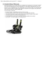
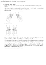
Upper coupler:
2.
Tilt cylinder
Upper coupler to excavator and double-acting tilt cylinders. In the upper coupler the gearbox is mounted via two
joints (so-called tilt shafts). The tilt shafts makes the tiltrotator tiltable. The tilt movement is achieved with the tilt
cylinders.
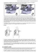
Gearbox:
1.
Gearbox
2.
Gear wheel
3.
Worm
4.
Hydraulic motor
5.
Tilt shafts
The link between the upper coupler and the attachment coupler, consists of a worm gear with a worm and a gear
wheel. The gear wheel is bolted to the attachment coupler with high tensile strength screws. The rotation is achieved
with an hydraulic motor driving the worm, which in turn rotates the gear wheel and thus the attachment coupler.
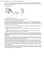
Attachment coupler:
1.
attachment coupler
2.
Locking pins
3.
Locking cylinder
4.
Check valve
5.
Indicator bar red (for open quick coupler)
6.
Indicator bar green (for locked/secured quick coupler)
7.
Front pin lock
™
The attachment coupler is used to lock the work tool by a hydraulic cylinder pushing a locking pin under the rear
pin of the work tool. This is done with a hydraulic cylinder ("the locking cylinder") and locking pins. For a secure
locking function, it is essential that the locking pins enclose the pins of the work tool. When the locking cylinder is
in its retracted position the lock is open and it is possible to connect or disconnect a work tool.
Front pin lock
™
is a safety function that locks the front bracket pin of the work tool in the attachment coupler when
the locking cylinder and locking pins are in the extended position. It prevents the work tool coming loose from the
coupler if the locking pins are accidently retracted above the rear bracket pin. This reduces the risk of dropping a
tool and causing an accident when changing tools. Front pin lock
™
is based on two locking wings engaging and
preventing the bracket pin from coming out of the front grip when the lock cylinder is in the extended/locked position.
Tools can be attached when the attachment coupler is both locked and open.
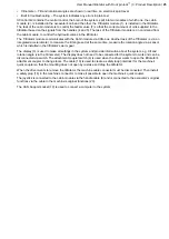
When the quick coupler is locked, this is indicated by a green indicator bar (right) protruding at the front edge by
the work tool shaft. When the quick coupler is open, a red indicator bar (left) is visible, see image below.
20
| User Manual tiltrotator with Front pin lock
™
| 3. Product Description
Summary of Contents for Tiltrotator Front pin lock X04
Page 2: ......
Page 16: ......
Page 26: ......
Page 48: ......
Page 54: ......
Page 55: ...Chapter 8 8 Environmental aspects Topics Environmental information ...
Page 63: ......
Page 64: ...Steelwrist AB Bäckvägen 18 192 54 Sollentuna Sweden 46 626 07 00 www steelwrist com 700347ENA ...


