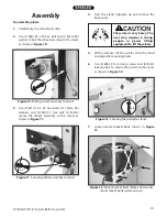
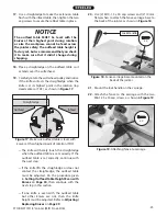
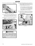
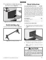
background image

ST1006/ST1011 8" Jointer (Mfd. Since 3/16)

-27-

Stock Inspection & 

Requirements

Follow these rules when choosing and jointing 

stock:

•  DO NOT joint or surface plane stock that 

contains large or loose knots. Injury to the 

operator or damage to the workpiece can occur 

if a knot becomes dislodged during the cutting 

operation.

• 

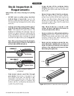
Jointing and surface planing with the grain is 

safer for the operator and produces a better 

finish.  Cutting against the grain increases the 

likelihood of kickback and workpiece tear-out. 

DO NOT cut against the grain! Cutting with the 

grain is feeding the stock across the cutterhead 

so the grain points down and back, as viewed 

from the front edge of the stock (see Figure 28).


Note: If the grain changes direction along the 

edge of the workpiece, decrease the depth of 

cut and make additional passes.

With Grain

Against Grain

CORRECT

INCORRECT

FEED DIRECTION

FEED DIRECTION

ROTATION

ROTATION

INFEED TABLE

OUTFEED TABLE

INFEED TABLE

OUTFEED TABLE

Figure 28. Proper grain alignment with the 

cutterhead.

• 

Scrape all glue off the workpiece before 

jointing. Glue deposits on the workpiece, hard 

or soft, will gum up the cutterhead and produce 

poor results.

• 

Remove foreign objects from the workpiece. 

Make sure that any stock you process with the 

jointer is clean and free of dirt, nails, staples, tiny 

rocks or any other foreign objects that could 

damage the cutterhead. These particles could 

also cause a spark as they strike the cutterhead 

and create a fire hazard.


Note:  Wood stacked on a concrete or dirt 

surface can have small pieces of concrete or 

stone pressed into the surface.

• 

Make sure all stock is sufficiently dried before 

jointing.  Wood with a moisture content over 

20% will cause unnecessary wear on the cutters 

and poor cutting results. Excess moisture can 

also hasten rust and corrosion.

• 

Make sure your workpiece exceeds the min-

imum dimension requirements, as shown in 

Figure  29, before processing it through the 

jointer, or the workpiece may break or kick-

back during the operation.

• 

Only process natural wood fiber through 

your jointer. Your jointer is designed to cut 

only natural wood stock. This machine is NOT 

designed to cut metal, glass, stone, tile,  prod-

ucts with lead-based paint, or products that 

contain asbestos—cutting these materials with 

a jointer may lead to injury.

10" Min.

1

/

4

" Min.

3

/

4

" Min.

10" Min.

1

/

2

" Min.

1" Min.

10" Min.

1

/

4

" Min.

3

/

4

" Min.

10" Min.

1

/

2

" Min.

1" Min.

Figure 29. Minimum stock dimensions for jointer.

Summary of Contents for ST1006

Page 1: ...PYRIGHT APRIL 2016 BY WOODSTOCK INTERNATIONAL INC WARNING NO PORTION OF THIS MANUAL MAY BE REPRODUCED IN ANY SHAPE OR FORM WITHOUT THE WRITTEN APPROVAL OF WOODSTOCK INTERNATIONAL INC Printed in China...

Page 2: ...h defects or other reproductive harm Some examples of these chemicals are Lead from lead based paints Crystalline silica from bricks cement and other masonry products Arsenic and chromium from chemica...

Page 3: ...hten Belt 25 OPERATIONS 26 Overview 26 Stock Inspection Requirements 27 Squaring Stock 28 Surface Planing 29 Edge Jointing 30 Bevel Cutting 31 Rabbet Cutting 32 ACCESSORIES 33 MAINTENANCE 34 General 3...

Page 4: ...use to collect glass metal liquids asbestos silica animal parts biohazards burning material ashes etc 5 Always disconnect power before servicing or cleaning 6 Do not expose to rain or wet areas 7 Kee...

Page 5: ...ton 2 Type Cardboard Box Content Stand Weight 157 lbs Length x Width x Height 38 x 20 x 28 in Electrical Power Requirement 240V Single Phase 60 Hz Prewired Voltage 240V Full Load Current Rating 15A Mi...

Page 6: ...in Cutterhead Speed 4800 RPM Knife Information Number of Knives 4 Knife Type HSS Single Sided Knife Length 8 in Knife Width 3 4 in Knife Thickness 1 8 in Knife Adjustment Jack Screws or Springs Table...

Page 7: ...Carton 2 Type Cardboard Box Content Stand Weight 157 lbs Length x Width x Height 38 x 20 x 28 in Electrical Power Requirement 240V Single Phase 60 Hz Full Load Current Rating 15A Minimum Circuit Size...

Page 8: ...r of Indexable Cutters 40 Cutterhead Speed 5350 RPM Cutter Insert Information Cutter Insert Type Curved Indexable Carbide Cutter Insert Length 15 mm Cutter Insert Width 15 mm Cutter Insert Thickness 2...

Page 9: ...le B Fence C Cutterhead Guard D Control Panel E Infeed Table F Infeed Table Adjustment Lever G Cutting Depth Scale H Infeed Table Lock I Mobile Base Lock Pedal J Outfeed Table Lock K Dust Port L Outfe...

Page 10: ...lever then tighten the table lock The infeed table will only move through the preset range of the positive stops To adjust the infeed table positive stops refer to Setting Infeed Table Height on Page...

Page 11: ...kshop kid proof DANGEROUS ENVIRONMENTS Do not use machin ery in areas that are wet cluttered or have poor lighting Operating machinery in these areas greatly increases the risk of accidents and injury...

Page 12: ...ct with moving parts or flying debris Make sure they are properly installed undamaged and working correctly BEFORE operating machine FORCING MACHINERY Do not force machine It will do the job safer and...

Page 13: ...fy workpiece is free of nails staples loose knots or other foreign material Workpieces with minor warping should be surface planed first with cupped side fac ing infeed table GRAIN DIRECTION Jointing...

Page 14: ...e must be connected to the correct size and type of power supply circuit or fire or electrical damage may occur Read through this section to determine if an adequate power supply circuit is available...

Page 15: ...e risk of electric shock The wire with green insulation with without yellow stripes is the equipment grounding wire If repair or replace ment of the power cord or plug is necessary do not connect the...

Page 16: ...erstood and fol lowed DO NOT risk your safety by not reading UNPLUG power cord before you do any assem bly or adjustment tasks Otherwise serious per sonal injury to you or oth ers may occur SUFFOCATIO...

Page 17: ...5 x 50 Wheel Stand 1 Hex Bolts M10 1 5 x 55 Wheel Stand 1 Flat Washer 8mm Wheel Stand 2 Flat Washers 10mm Wheel Stand Carriage Pedestal 6 Hex Nuts M10 1 5 Wheel Stand 2 Cap Screws M8 1 25 x 25 Jointer...

Page 18: ...1MM APART 5mm 10mm 20mm 15mm 25mm 40mm 30mm 35mm 45mm 50mm 60mm 55mm 70mm 65mm 75mm W A S H ER DIAM E T E R 5 8 W A S H ER DIAM E T E R 9 16 1 2 W A S H ER DIA M E T E R W A S H ER DIA M E T E R 12mm...

Page 19: ...g Disposable rags Cleaner degreaser WD 40 works well Safety glasses disposable gloves Plastic paint scraper optional Basic steps for removing rust preventative 1 Put on safety glasses 2 Coat the rust...

Page 20: ...ironment The physical environment where the machine is operated is important for safe operation and longev ity of machine components For best results operate this machine in a dry environment that is...

Page 21: ...10 1 5 hex nuts to further secure the wheel assembly to the stand as shown in Figure 11 5 With assistance lift the jointer onto the stand and align the mounting holes Figure 10 Bolting wheel assembly...

Page 22: ...zontally as needed to align the pulleys and tighten the motor mount bolts 12 Re install the V belt on the pulleys 13 Pull down on the motor with one hand to keep tension on the V belt and tighten the...

Page 23: ...table is set correctly If the outfeed table is set correctly continue with the next step If the knife lifts the straightedge or does not contact the straightedge the outfeed table must be adjusted Do...

Page 24: ...ded before using the jointer Failure to do this will greatly increase the chances of a serious injury when operating the jointer 26 Test that the cutterhead guard is working cor rectly by pulling it b...

Page 25: ...ng of the dust collector 2 hose type and length between the dust collector and the machine 3 number of branches or wyes and 4 amount of other open lines throughout the system Explaining how to calcula...

Page 26: ...al problem during the test run immediately stop the machine disconnect it from power and fix the problem BEFORE operating the machine again The Troubleshooting table in the SERVICE section of this man...

Page 27: ...to Page 43 Depth of Cut Scale Calibration refer to Page 47 Fence Stop Accuracy refer to Page 48 Recommended Adjustments Tighten Belt The final step in the setup process must be done after approximatel...

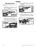
Page 28: ...s fence tilt if necessary 4 Adjusts infeed table height to set depth of cut per pass 5 Puts on safety glasses respirator and ear protec tion 6 Locates push blocks 7 Starts jointer 8 Holds workpiece fi...

Page 29: ...ll gum up the cutterhead and produce poor results Remove foreign objects from the workpiece Make sure that any stock you process with the jointer is clean and free of dirt nails staples tiny rocks or...

Page 30: ...laner Previously Surface Planed Face 2 Surface Plane On a Thickness Planer The opposite face of the workpiece is surface planed flat with a thickness planer see Figure 31 3 Edge Joint On The Jointer T...

Page 31: ...les during the entire cut IMPORTANT Keep hands at least 4 away from cutterhead during the entire cut Instead of allowing a hand to pass directly over cutter head lift it up and over cutterhead and saf...

Page 32: ...4 Start jointer 5 Place workpiece firmly against fence and infeed table IMPORTANT To ensure workpiece remains stable during cut concave sides of workpiece must face toward table and fence 6 Feed workp...

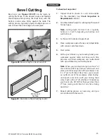
Page 33: ...ypically between 1 16 and 1 8 depending on hardness and width of stock 3 Set fence tilt to desired angle of cut 4 Place workpiece against fence and infeed table with concave side face down 5 Start joi...

Page 34: ...ed table height to desired cutting depth for each pass IMPORTANT For safety reasons cutting depth should never exceed 1 8 per pass 3 Remove cutterhead guard 4 Set fence to 90 and near front of jointer...

Page 35: ...ng bevels and a diagonal stone for flat edges Figure 43 D1123 Knife Honer The following lathe accessories may be available through your local Woodstock International Inc Dealer If you do not have a de...

Page 36: ...any specific instructions given in this section Note This maintenance schedule is based on average daily usage Adjust the maintenance schedule to match your usage to keep your planer running smoothly...

Page 37: ...nsure workpiece is suitable for jointing Page 27 2 Reduce feed rate 3 Reduce depth of cut 4 Sharpen replace knives Page 38 rotate replace inserts Page 41 5 Clear blockages move machine closer to dust...

Page 38: ...in left in workpiece 1 Wood has high moisture content 2 Dull knives inserts 1 Ensure wood moisture content is less than 20 Allow to dry if necessary 2 Replace rotate knives inserts Page 38 Long lines...

Page 39: ...ves can be inspected with a straightedge to ensure that they are set even with the outfeed table at their highest point in the cutterhead rotation or top dead center TDC To inspect the knives 1 DISCON...

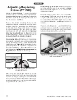
Page 40: ...ibed in Setting Outfeed Table Height on Page 45 for this method to work correctly Adjusting Replacing Knives ST1006 Figure 49 Example of knife setting jig positioned over cutterhead knife Middle Pad F...

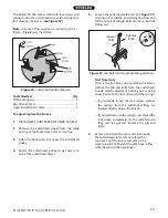
Page 41: ...or sawdust Coat the knives and gibs with a metal protectant then fit the gibs back in the cutterhead with the new knives The Model ST1006 comes with both jack screws and springs inside the cutterhead...

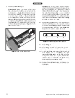
Page 42: ...the knife setting jig feet evenly against the cutterhead depending on which method you are using Tighten the gib bolts just tight enough to hold the knife in place Repeat on the other side of the cut...

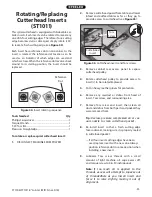
Page 43: ...to expose cutterhead pulley 4 Rotate cutterhead pulley to provide access to insert s to be rotated replaced 5 Put on heavy leather gloves for protection 6 Remove any sawdust or debris from head of in...

Page 44: ...as shown in Figure 57 rotate the cutterhead if necessary Figure 56 Table positive stop bolts Positive Stop Bolts 5 Place the straightedge in the positions shown in Figure 58 In each position the stra...

Page 45: ...d that you double check the current table posi tions to make sure that they really need to be adjust ed before starting The tables have four eccentric bushings under each corner that allow the tables...

Page 46: ...outfeed table is parallel with the cutterhead Black Lines Represent Straightedge Positions from Overhead View Figure 62 Straightedge positions for verifying if outfeed table is parallel with cutterhea...

Page 47: ...nsert at top dead center Top Dead Center Bottom Dead Center ST1006 ST1011 3 Knife Style Cutterhead Only Correctly set knife heights Refer to Adjusting Replacing Knives ST1006 on Page 38 for detailed i...

Page 48: ...tion so it will not move during operation Figure 66 Positive stop bolts for infeed table Top Height Bottom Height Jam Nuts Calibrating Depth Scale To calibrate the depth scale 1 DISCONNECT MACHINE FRO...

Page 49: ...verify the angle with a 45 square 5 Retighten the jam nut loosened in Step 2 To set 90 fence stop 1 Loosen the set screw in the plunger lock collar shown in Figure 70 and loosen the fence tilt lock 2...

Page 50: ...in Figure 73 3 Press down on motor to keep tension on belt Motor Pulley Approximately 1 4 Deflection Cutterhead Pulley Figure 74 Correct belt deflection when properly tensioned Replacing Belt 1 DISCO...

Page 51: ...WER 2 Open the back cover and remove the belt guard 3 Visually check the alignment of the two pulleys to make sure that they are aligned and that the V belts are straight up and down see Figure 75 If...

Page 52: ...8 Jointer Mfd Since 3 16 ELECTRICAL COMPONENTS Control Panel Assembly STOP Reset Switch ON Switch Magnetic Switch Assembly Contactor Thermal Overload Relay To Control Panel To Motor To Power Source M...

Page 53: ...2 5L3 2T1 4T2 6T3 13no 14no A2 A1 98 97 96 95 Ground Hot Ground Hot 6 20 PLUG 240 VAC Bl Contactor Thermal Overload ON Switch Top STOP Reset Switch 2 4 1 3 5 Hot Hot Ground 240 VAC G 240V MOTOR Start...

Page 54: ...8 9 10 11 12 13 14 15 16 17 18 19 20 21 22 23 29 30 32 33 34 35 36 37 38 39 42 43 44 45 46 47 48 49 50 51 52 53 54 55 56 57 58 59 60 61 62 12 35 3 35 2 35 4 35 1 35 5 24 25 26 27 28 28 2 28 1 28 3 28...

Page 55: ...T1006018 CARRIAGE BOLT 5 16 18 X 3 4 43 XST1006043 FLAT WASHER 12MM 19 XST1006019 CARRIAGE BOLT 5 16 18 X 1 1 4 44 XST1006044 CLEVIS PIN 20 XST1006020 FLAT WASHER 5 16 45 XST1006045 HEX BOLT M8 1 25 X...

Page 56: ...142 143 144 145 146 147 149 150 151 152 153 154 155 173 174 175 176 177 178 179 180 181 182 183 184 185 186 187 188 189 190 191 192 193 194 195 196 197 198 199 200 201 202 203 204 205 206 207 208 209...

Page 57: ...73 XST1006173 CAP SCREW M8 1 25 X 80 125 XST1006125 FLAT WASHER 6MM 174 XST1006174 GUARD CLAMP 126 XST1006126 TILT SCALE POINTER 175 XST1006175 CUTTERHEAD GUARD 127 XST1006127 FLAT WASHER 6MM 176 XST1...

Page 58: ...10 230 XST1006230 START BUTTON 210 XST1006210 PIVOT BRACKET 231 XST1006231 STOP BUTTON 211 XST1006211 ADJUSTING BLOCK 232 XST1006232 CONTROL PANEL FACE 212 XST1006212 HEX NUT M12 1 75 233 XST1006233 T...

Page 59: ...DESCRIPTION REF PART DESCRIPTION 301 XST1006301 FENCE CUTTERHEAD WARNING LABEL 308 XST1006308 DECORATIVE STRIPE TAPE 302 XST1006302 CUTTERHEAD GUARD WARNING LABEL 309 XST1006309 DISCONNECT POWER LABEL...

Page 60: ...at the defect resulted from causes not within the scope of Woodstock International Inc s warranty then the original owner must bear the cost of storing and returning the product This is Woodstock Inte...

Page 61: ...to a friend ______ Yes ______ No 6 What is your age group ______ 20 29 ______30 39 ______ 40 49 ______ 50 59 ______60 69 ______ 70 7 What is your annual household income ______ 20 000 29 000 ______ 3...

Page 62: ...TAPE ALONG EDGES PLEASE DO NOT STAPLE FOLD ALONG DOTTED LINE FOLD ALONG DOTTED LINE WOODSTOCK INTERNATIONAL INC P O BOX 2309 BELLINGHAM WA 98227 2309 Place Stamp Here...

Page 63: ......

Page 64: ......

Reviews: