ST1006/ST1011 8" Jointer (Mfd. Since 3/16)
-41-
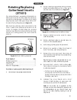
This spiral cutterhead is equipped with indexable car-
bide inserts. Each insert can be rotated to reveal any
one of its four cutting edges. Therefore, if one cutting
edge becomes dull or damaged, simply rotate it 90˚
to reveal a fresh cutting edge (see Figure 54).
Each insert has a reference dot on one corner. As the
insert is rotated, the reference dot location can be
used as an indicator of which edges are used and
which are new. When the reference dot revolves back
around to its starting position, the insert should be
replaced.
Rotating/Replacing
Cutterhead Inserts
(ST1011)
Tools Needed
Qty
Phillips Screwdriver ............................................................. 1
Torque Wrench ...................................................................... 1
T-20 Torx Bit ............................................................................ 1
Precision Straightedge ....................................................... 1
Figure 54. Insert rotating sequence.
Reference
Dot
To rotate or replace spiral cutterhead insert:
1. DISCONNECT MACHINE FROM POWER!
Figure 55. Cutterhead inserts and Torx screws.
Cutterhead
Insert
Torx
Screw
3. Remove cabinet rear access panel to expose
cutterhead pulley.
4. Rotate cutterhead pulley to provide access to
insert(s) to be rotated/replaced.
5. Put on heavy leather gloves for protection.
6. Remove any sawdust or debris from head of
insert, Torx screw, and surrounding area.
7. Remove Torx screw and insert, then clean all
dust and debris from both parts and pocket they
were removed from.
Tip:
Use low-pressure compressed air or vac-
uum nozzle to clean cutterhead pocket.
8. Re-install insert so that a fresh cutting edge
faces outward, making sure it is properly seated
in cutterhead pocket.
— If all four insert cutting edges have been
used, replace insert with a new one. Always
position reference dot in same position when
installing a new insert.
9. Lubricate Torx screw threads with a small
amount of light machine oil, wipe excess off,
and torque screw to 48–50 inch/pounds.
Note:
If too much oil is applied to the
threads, excess will attempt to squeeze out
of threadedhole as you install insert and
force it to raise slightly, making it out of
alignment.
2. Remove cutterhead guard from table, and lower
infeed and outfeed tables as far as they go, to
provide access to cutterhead (see Figure 55).

