-20-
ST1006/ST1011 8" Jointer (Mfd. Since 3/16)
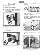
14. Use (2) M6-1 x 10 flange bolts, (2) M6-1 hex
nuts, and (2) 6mm flat washers to install the belt
guard, as shown in Figure 15.
15. Replace the cover on the back of the jointer
stand.
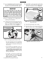
16. Use (2) M6-1 x 20 cap screws to attach the rab-
bet table to the front of the jointer, as shown
in Figure 16, but do not fully tighten the cap
screws yet.
9. Check the alignment of the pulleys to make sure
the V-belt is straight up and down.
— If the pulleys are aligned, go to Step 13.
— If the pulleys are NOT aligned, follow Steps
10–12.
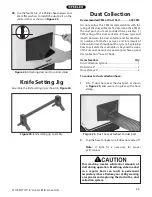
10. Remove V-belt and loosen motor mount bolts
(see Figure 13).
11. Shift the motor horizontally as needed to align
the pulleys, and tighten the motor mount bolts.
12. Re-install the V-belt on the pulleys.
13. Pull down on the motor with one hand to keep
tension on the V-belt, and tighten the motor
bracket bolts with your other hand.
Note:
DO NOT use a mechanical device to push
the motor down farther than you can by hand or
you will overtighten your V-belt, which will lead to
shortened bearing life in the motor or cutterhead.
Figure 15. Installing the belt guard.
x 2
Figure 16. Attaching rabbet table to jointer.
x 2
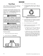
The belt guard MUST be installed before oper-
ating the jointer or the moving V-belt will be
exposed, creating an entanglement hazard at
the back of the jointer.
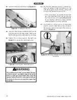
8. Put the V-belt on motor pulley, then roll it onto
the cutterhead pulley, as shown in Figure 14.
Figure 14. Rolling the V-belt onto cutterhead pulley.

