


12
During the heating season, a constant
volume of water must be maintained inside
the heating system. When topping up water,
care must be taken that no air is sucked into
the system. Water must never be let out of
the boiler or the heating system, unless it is
absolutely essential, such as before repairs,
etc. Draining water and refilling the system
ial, such as before repairs, etc with new water
increases the risk of corrosion and formation
of incrustation.
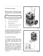
Please note
Filling or topping up water to the heating
system must always be done with the boiler
cold or cooled down; otherwise the boiler
block may crack!
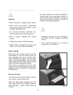
Operation and controls
Starting a fire
Check on the thermometer whether there is
enough water in the heating system. Open
the shutting valve between the boiler and the
heating system. Spread paper on top of the
clean stoker and then enough finely chopped
wood. Open the flue flap in the chimney
adapter and shut the stoking door. Light the
paper through the open ashtray door and fully
open the regulating flap in the ashtray door.
The fire has caught up enough stoke a layer
of main fuel on top of the burning firewood.
When the fire is powerful enough, stoke more
fuel right up to the bottom edge of the stoking
door and level it into.
Provide an even layer throughout the entire
boiler depth. If the fuel suddenly turns into
dark red blaze, open partially the secondary
air supply rosette in the stoking door. When
the flame turns yellow, shut the secondary air
supply rosette again. When the boiler has
reached the required output, it is suitable to
partially shut the flue thrust flap to prevent
heat from unnecessarily escaping into the
chimney.
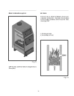
•
Do not start the boiler without connecting
the boiler to the chimney.
•
Control
chimney
connections
before
starting the boiler.
•
Adjust the chimney blow as requested level.
If chimney blow is under mentioned levels
try not to use the boiler.
Setting the outlet water temperature
When the required outlet water temperature is
say 60 °C, heat up the boiler to a temperature
for instance 5 °C higher than the required
temperature of 60 °C (measured on the
thermometer on the boiler outlet pipe). Then
turn the control knob to 65 °C and check
whether the chain is stretched and the
regulating hatch completely shut. This position
of the chain and regulating hatch is fine-
adjusted y turning the control knob. Then let
the regulation process work. When the water
temperature drops, the regulating hatch will
start opening by the tension applied by the
regulator on the chain. When the water
temperature suddenly rises, the regulating
hatch will start opening. And the hot water
temperature on the boiler outlet is controlled.
Stoking
First shut the regulating hatch; this will shut
supply of combustion air into the boiler. Then
open the chimney flap completely. Partially
open the stoking door and wait until all
combustion gases have been sucked from
the combustion chamber into the chimney.
Summary of Contents for ARTA series
Page 1: ...REV 01 2012 122088 ...
Page 5: ...5 Boiler dimensions ...
Page 6: ...6 Boiler packaging ...
Page 7: ...7 Technical parameters ...
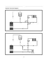
Page 22: ...22 Hydraulic Connection Diagrams ...
Page 24: ...24 ARTA boiler parts ...
Page 25: ...25 ARTA boiler spare parts lists ...
Page 26: ...26 ...
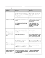
Page 27: ...27 Troubleshooting ...
Page 28: ...28 NOTES ...


