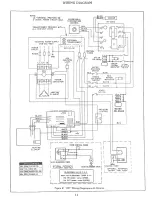
CP-1 CONTROL PACKAGE
CP-1 CONTROL PACKAGE INSTALLATION
AND OPERATION
The CP-I Control Package is completely automatic in
operation... room temperature is thermostatically con-
trolled by the Steamist ST-200C Solid State Temperature
Control System in conjunction with the generator’s steam
solenoid valve. No attendant required... set it, forget it.
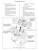
The “rapid response” ST-200C Temperature Control Sys-
tem is made up of three components: Temperature Sensor
Probe (Figure 3), Temperature Control Panel (Figure 4),
and System Control Module (Figure 5). After installation
of the ST200C is complete the steamroorn temperature
will automatically be maintained within 1-1/2 F of the
desired setting.
NOTE:
This control is not an ON/OFF switch, it is used
in conjunction with the Steam Solenoid Valve. The steam
generator cannot be turned OFF with this device.
A. Pre - Construction Considerations
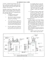
Choose a location to mount the Temperature Con-
trol Panel. If only a manager or limited group will
be in charge of controlling the steambath tempera-
ture, a utility area may be appropriate.
If steambathers will be permitted to adjust the tem-
perature, choose a convenient location outside the
steamroom door.
Mount the Temperature Control Panel OUTSIDE
the steamroom. Mount the Temperature Sensor
Probe INSIDE the steamroom.
WARNING:
All electrical power to the steam gen-
erator
MUST
be turned
OFF
before proceeding
with installation.
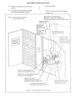
B. CP-1 Control Package Rough-in
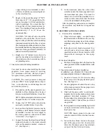
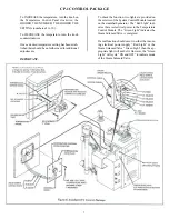
The 3 wire cable for Temperature Control Panel to
be used during installation of the ST200C Solid
State Temperature Control System is low voltage;
18 or 22 AWG wire recommended. Every attempt
should be made to match the color wire of the Tem-
perature Control Potentiometer lead wires (P1
white, P2 black, and P3 red) to the 3 wire cable.
Install a metal two-gang switch box rotated 90
(refer to Figure 4). Install an inverted strain re-
lief clamp and feed the 3 wire cable into the
two -gang box. Run the 3 wire came from the
switch box to the steam generator’s location.
1)
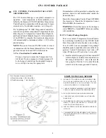
STEPS TO INSTALL SENSOR
SEPARATE TWO WIRES OF CABLE (COMING THRU
WALL FROM GENERATORS ST 200C CIRCUIT
BOARD, TERMINAL #2 AND #4) APPROX. 2", STRIP
AND TWIST APPROX. 1/2" OF BARE WIRE.
TAKE NEW SENSOR ASSEMBLY AND TWIST WIRES
TO WALL CABLE AND SECURE WITH WIRE NUTS.
PEEL OFF ADHESIVE BACKING FROM SENSOR.
CAREFULLY APPLY SILICONE SEALANT AROUND
REAR EDGE.
FEED WIRES BACK INTO WALL AND PRESS SENSOR
FIRMLY TO WALL (BE CAREFUL TO ALIGN PLATE
HOLES WITH ANCHOR HOLES).
INSTALL SCREWS, AND SNAP CHROME COVER BACK
IN PLACE.
TEMPERATURE SENSOR ASSEMBLY MUST FORM A
100% WATER TIGHT SEAL TO THE WALL USING SILI-
CONE SUPPLIED.
1)
2)
3)
4)
5)
6)
7)
Note: Location of sensor is as follows:
a) Single tier seating - 6 feet above floor.
b) Double tier seating - 7 feet above floor.
III
4
Summary of Contents for HC-10
Page 1: ...HEAVY COMMERCIAL STEAMBATH GENERATOR OWNERS MANUAL Models HC 9 Thru HC 18 3 98 Pub No 400 G ...
Page 12: ......
Page 13: ......
Page 14: ......


