CP-1 CONTROL PACKAGE
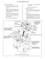
3) System Control Module
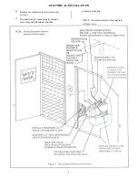
Remove screws securing cover to Sys-
tem Control Module and remove cover
(Figure 5).
a.
Feed the 3 wire cable through the top
strain relief. three inches into the control
module. Attach wires as shown in the
blowup (Figure 5).
Feed the 2 wire cable through the lower
strain relief, three Inches into the control
module. Attach wires as shown in the
blowup (Figure 5).
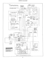
Check that all connections are made
b.
c.
d.
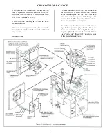
in accordance with Wiring Diagram
(See Figure 7.)
e. Replace control module cover.
D. Steam Solenoid Valve
There is no installation required for the steam
solenoid valve. it is factory installed and
wired.
E. Operation
The temperature of the steambath is regu-
lated automatically by the ST-200C Tempera-
ture Control System which turns “On or Off”,
the Steam Solenoid Valve located on the
steam generator allowing steam to enter the
room.
6
Summary of Contents for HC-10
Page 1: ...HEAVY COMMERCIAL STEAMBATH GENERATOR OWNERS MANUAL Models HC 9 Thru HC 18 3 98 Pub No 400 G ...
Page 12: ......
Page 13: ......
Page 14: ......


