background image

STEALTH DIGI-TIG 180 DC PULSE PFC MV


3.2  Duty Cycle and Over-heating


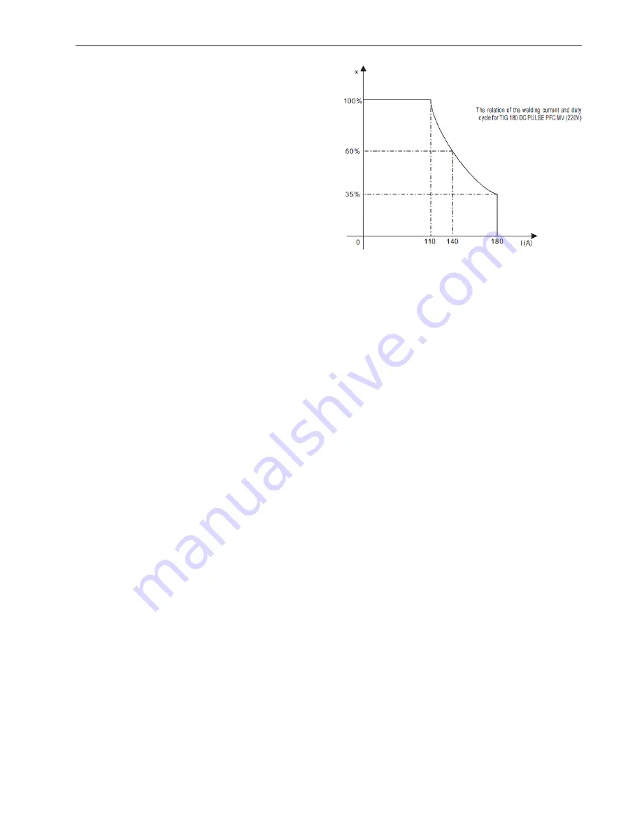
The letter ‘X’ stands for duty cycle, 


which is defined as the proportion


of the time that a machine can work


continuously within a certain time (10


minutes). The rated duty cycle means


the proportion of the time that a


machine can work continuously within


10 minutes when it outputs the rated


welding current.


The relation between the duty cycle ‘X’ 


and the output welding current ‘I’ is 


shown as the figure on the right.


If the welder is over-heating, the IGBT over-heating protection unit inside will send a


message to cut output welding current and illuminate the pilot lamp on the front 

   panel.


At this point, the machine should be turned off for 15 minutes to cool the fan. When 


operating the machine again, the welding output current or the duty cycle should be 

   reduced.


3.3   Movement and Placement


Please take care when moving it the machine and keep it level.


It also can be moved by the handle on the top. Place the machine securely when in


the right location. When moving using a forklift, ensure the arm lengths are long 


enough to reach outside the machine to safely lift.


The movement may result in the potential danger or substantive hazard, so please 


make sure that the machine is in a safe position before using it.


3.4  Power Supply Input Connection


TIG DC PULSE PFC MV welding machine’s power supply connects to 110/220V.


When the power supply voltage is over the safe working voltage, there are over-voltage 


and under-voltage protection inside the welder. The alarm light will illuminate and, at 


the same time, the current output will be cut off.


If the power supply voltage continually goes beyond the safe work voltage range, it will


shorten the machine’s life-span. The below measures can be used:


•  Change the power supply input net (connect the welder with the stable power supply


  voltage of distributor).


•  Switch on the machines using power supply at the same time.


•  Set the voltage stabilisation device in the front of power cable input.

INSTALLATION AND ADJUSTMENT 

10 

§3.2 Duty cycle & Over heat 

The letter “X”  stands for duty 

cycle, which is defined as the proportion 

of the time that a machine can work 

continuously within a certain time (10 

minutes). The rated duty cycle means 

the proportion of the time that a 

machine can work continuously within 

10 minutes when it outputs the rated 

welding current.   

The relation between the duty cycle “X” and the output welding current “I” is shown as the 

right figure. 

   If the welder is over-heat, the IGBT over-heat protection unit inside it will  output an 

instruction to cut output welding current, and brighten the over-heat pilot lamp on the front panel. 

At this time, the machine should be relaxed for 15 minutes to cool the fan. When operating the 

machine again, the welding output current or the duty cycle should be reduced. 

§3.3 Movement and placement 

Please take care for the welder when moving it, and do not make it sloped. 

It also can be moved by the handle on the top of the welder. Place the welder  well when 

moving it to the right position. When the machine gets to the destination, it needs to be fixed up to 

avoid gliding. 

When using forklift, its arm length must be long enough to reach the outside so as to ensure 

lifting safely. 

   The movement may result in the potential danger or substantive hazard, so please make sure 

that the machine is on the safe position before using it.   

§3.4 Power supply input connection 

TIG DC PULSE PFC MV welding machines’ power supply connects to 110/220V. 

When the power supply voltage is over the safe work voltage,  there are over voltage and 

12

Summary of Contents for 9011H

Page 1: ...Part No 9010H DIGI TIG 180 DC PULSE PFC MV OPERATOR S MANUAL...

Page 2: ...s Manual completely before attempting to use this equipment Save this manual and keep it handy for quick reference Pay particular attention to the safety instructions provided for your protection Cont...

Page 3: ...ECTION 12 3 5 POLARITY CONNECTION MMA 13 3 6 ASSEMBLING THE EQUIPMENT TIG 13 4 OPERATION 14 4 1 MACHINE CONTROLS 14 4 2 CONTROL PANEL 15 4 3 ARGON ARC WELDING OPERATION 18 4 3 1 TIG WELDING 4T OPERATI...

Page 4: ...re as follows It is q operation after taking several necessary protection measures 1 2 Arc Welding Damage The following signals and word explanations are to some damages for your body or others on the...

Page 5: ...xic gas and other irritating products Shielding gases used for arc welding can displace air and cause injury or death Always use ventilation especially in confined areas to insure breathing air is saf...

Page 6: ...AFETY an explosion even though they have been cleaned Vent hollow castings or containers before heating cutting or welding They may explode Sparks and spatter are thrown from the welding arc Wear oil...

Page 7: ...MF as far as possible by applying the following procedures Route the electrode and work cables together Secure them with tape when possible All cables should be stored away from the operator Never coi...

Page 8: ...please refer to 3 5 2 For DC TIG DCEP is used normally workpiece connected to positive polarity while torch connected to negative polarity This connection has many characters such as stable welding a...

Page 9: ...ng machine MMA 2 3 Working Principle The working principle of TIG DC PULSE PFC MV series welding machines is shown as following figure Single phases work frequency AC 110 220V 50 Hz is rectified into...

Page 10: ...STEALTH DIGI TIG 180 DC PULSE PFC MV 8 67 34 10 0 600 I2 A U2 V Working point Volt ampere characteristic The relation between the conventional loading voltage and welding current 10...

Page 11: ...0A 60 85A 100 65A 30 110A 60 80A 100 65A 35 180A 60 140A 100 110A 25 180A 60 120A 100 100A 0 99 MMA 33 3 2 17 3 7 MMA 26 5 5 8 1 220 230 240 Frequency Hz Rated Input Current A Rated Input Power Kw Pow...

Page 12: ...work voltage range it will shorten the machine s life span The below measures can be used Change the power supply input net connect the welder with the stable power supply voltage of distributor Switc...

Page 13: ...s of 2 wires pedal control of 3 wires and the aero socket of 14 leads Consumable parts for TIG torch such as tungsten electrode tip gas nozzle electrode shield short long contact your supplier quoting...

Page 14: ...er is turned off 6 Power source input To connect power source 7 Shield gas input joint To connect one head of the gas hose while the other head of which is connected to argon gas cylinder 1 Positive o...

Page 15: ...iew of the main settings needed for day using the TIG DC PULSE PFC MV control panel as an example You will find a deta of these settings in the following section 1 TIG mode selecting key 2 step mode 4...

Page 16: ...ting Tup Upslope time Unit S Setting range 0 10 Factory setting Iw Welding current Unit A TIG 180 DC PULSE PFC MV 5 110 110V 5 180 220V TIG 200 DC PULSE PFC MV 5 130 110V 5 220 220V Ib Base current Un...

Page 17: ...g parameter Parameter Setting range Arc force 0 10 Hot start 0 10 4 Power Alarm indicator Light up if the welder overheat 5 Welding current and other parameter display Before start of welding Indicate...

Page 18: ...crater current 5 100 of main current t6 Loosen the gun switch stop arc and keep the argon flowing t6 t7 Post flow time adjustment range of post flow time 0 10S t7 Electromagnetic valve is closed and s...

Page 19: ...me adjustment range of post flow time 0 10S Introduction 0 Press and hold the gun switch electromagnetic gas valve is turned on The shielding gas starts to flow 0 t1 Pre flow time adjustment range of...

Page 20: ...ing area color argent golden blue red grey grey black Protect effect best better good bad worst The relation of welding area color protect effect of Ti alloy Welding area color bright argent orange ye...

Page 21: ...ozzle diameter mm Gas flow rate L min 1 10 100 4 9 5 4 5 101 150 4 9 5 4 7 151 200 6 13 6 8 201 300 8 13 8 9 tungsten electrode diameter mm sharpened of the electrode diameter mm angle of cone backgro...

Page 22: ...e the above parameters originate from Welding Dictionary P150 Volume 1 of Edition 2 MAINTENANCE AND TROUBLESHOOTING 4 5 Operation Environment Parameters of piping back sealing welding for mild steel D...

Page 23: ...during welding and there is at least 30cm free distance between the machine and wall 4 6 Operation Notices Read all notes carefully before attempting to use this equipment Connect the ground wire wit...

Page 24: ...ct your distributor if there are no parts to hand After switching on power watch and listen to check the arc welding machine is not shaking whistling or giving out an unusual odour If so investigate a...

Page 25: ...ve already been carefully checked Do not allow anyone unauthorised to make any alterations to the equipment Maintenance work must be carefully undertaken If any wire becomes loose or misplaced it may...

Page 26: ...tromagnetic valve damaged Change Front panel gas test is on Turn off Blockage in the valve Remove 7 Gas continually flows Electromagnetic valve damaged Change Front panel gas test adjustment knob is d...

Page 27: ...STEALTH DIGI TIG 180 DC PULSE PFC MV 5 3 Main Electrical Diagram MAINTENANCE AND TROUBLESHOOTING 5 3 Electrical principle drawing 110 220V AC 27...

Page 28: ...Specialised Welding Products Ltd Unit 1 Farringdon Industrial Centre Farringdon Nr Alton Hampshire GU34 3DD UK tel 44 0 1420 588180 fax 44 0 1420 588184 email sales swp uk net...

Reviews: