3-8
System Preparation
Chapter 3 - Installation
STARPLUS STSe - Installation Manual
August 2005
Power Line Surge Protection
The AC outlet should be equipped with a power surge protection device or UPS. Systems using
such devices are more resistant to damage from power line surges than unprotected systems.
Power line surges often occur during normal operations and during violent thunderstorms.
Installation of a surge protector meeting the specifications described in the following
paragraph may prevent or minimize the damage resulting from power line surges.The isolation
transformer/surge protector should be: 15 amp self-contained unit that plugs into a standard
grounded 117V AC wall outlet. The wall outlet must be designed to accept a 3-prong plug (two
parallel blades and a ground pin). The protector should be fast and capable of protecting
transients greater than 200 volts.
Lightning Protection
The system provides secondary protection per UL 1459 specifications. Primary protection
circuitry is the installer’s responsibility and should be installed per National Electric Code (NEC).
KSU AC Power Plug
Before plugging the KSU power cord in the AC source (grounded, 3-prong AC outlet required):
1. Verify the power switch of the BKSU is off.
2. Plug the KSU power cord into the AC outlet.
3. Turn the power switch on.
Cable Connections
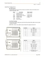
Champ connectors are mounted on the side of each
STSe
BKSU and EKSU - one for CO and Miscellaneous connections,
one for Station connections, and one to connect the BKSU
and EKSU.
PCB Handling and General Installation
The system cards contain digital circuitry which are extremely reliable, but can be damaged by
exposure to excessive static electricity. When handling PCBs, a grounded wrist strap should be
used to protect boards from static discharges. Also, use common sense when handling PCBs.
EXAMPLE
-- Do not place a PCB in locations where heavy objects might fall on the PCB and
damage components.
Inserting a PCB
1. Hold PCB with components facing left, align top and bottom edge of PCB in card guides.
2. Slide the card into the system seat the PCB firmly into the backplane connector.
3. To remove a PCB, reverse the process.
DO NOT install or remove any boards with power applied.
Make sure power is turned off prior to installation or removal of the PCBs
To EKSU
Champ Connectors
To CO
or
M
isc
To St
a
Summary of Contents for STSe Key System
Page 1: ...August 2005 Issue 1 0 STARPLUS STSe Key Systems Installation Manual TM...
Page 4: ......
Page 10: ...vi Figures STARPLUS STSe Installation Manual August 2005...
Page 12: ...viii Tables STARPLUS STSe Installation Manual August 2005...
Page 14: ...N O T E S...
Page 22: ...N O T E S...
Page 30: ...N O T E S...
Page 68: ...3 40 Door Box Chapter 3 Installation STARPLUS STSe Installation Manual August 2005...
Page 70: ...N O T E S...
Page 94: ...iv Index STARPLUS STSe Installation Manual August 2005...


