background image

Door Box

3-39

Chapter 3 - Installation

STARPLUS STSe - Installation Manual

August 2005

Door Box

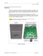
The Door Box is an intercom unit that can be installed at an entrance to a building. The unit 
houses a Call Button that a visitor can use for two-way communication with a person inside 
the building who has a keyset with a call coverage flexible button associated with the Call 
Box.

Alternatively, the unit can be mounted beyond the reach of visitors and wired to a 
conventional doorbell switch, which then serves as the Call Button. This option helps protect 
the Door Box from damage that might be caused by rough handling by visitors or vandals. 
The unit is wired into a DTIB port in the KSU.

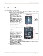
Figure 3-17: Door Box

SITE


LOCATION

 … Installing the Door Box in an enclosed area that offers 

environmental protection is recommended.

Front View

Back View with Cover Removed

Contacts for

a DTIB card

Contacts for

a doorbell switch

Summary of Contents for STSe Key System

Page 1: ...August 2005 Issue 1 0 STARPLUS STSe Key Systems Installation Manual TM...

Page 2: ...eliable but is not warranted to be true in all cases STARPLUS is a Registered trademark of VODAVI Technology Inc mlj 2005 Issue Release Date Changes Page 1 0 8 05 Initial Release LIFE SUPPORT APPLICAT...

Page 3: ...as met all safety requirements and was found in compliance with the Underwriters Laboratories UL 1459 This system is authorized to bear the NRTL C marking Notice of Compliance The STSe System complies...

Page 4: ......

Page 5: ...Power Supply 1 6 Extension Boards 1 6 Digital Telephone Interface Board 8 port 1 6 Single Line Telephone Interface Board 4 port 1 7 CO Interface Boards 1 7 Loop Start CO Line Interface Board 1 7 T1 In...

Page 6: ...PCB 3 8 Card Slot Configuration 3 9 Board Capacity 3 9 Card Slot Positions 3 9 BKSU Main Board Unit Assembly 3 10 Main Board Unit 3 10 Initialize Default Settings 3 10 Retain Database 3 10 Digital Te...

Page 7: ...ne Telephone Wiring 3 35 Keyset Headset Installation 3 36 Wall Mounting the Digital Keyset 3 36 Installing a Headset 3 37 System Checkout 3 38 Preliminary Procedures 3 38 Power Up Sequence 3 38 Door B...

Page 8: ...4 Basic Format for Commands 4 14 Examples 4 14 Remote System Monitor 4 14 General Overview 4 14 Monitor Password 4 15 Help Menu 4 15 Dump Memory Data 4 15 Event Trace Mode 4 16 Modify Memory Command 4...

Page 9: ...4 Module Installation 3 22 Flash Based Voice Mail Card 3 24 Hard Drive Based Voice Mail Card 3 25 MODU Installation Location 3 26 U2 and U3 EPROM Locations 3 27 Digital Station Jack Wiring 3 32 SLA Si...

Page 10: ...vi Figures STARPLUS STSe Installation Manual August 2005...

Page 11: ...ecifications 2 8 Loop Limits 2 8 Dimensions and Weights 2 8 T1 Switch Positions 3 17 T1 Ordering Specifications 3 17 T1 Ordering Information 3 17 Call Routing Criteria 3 18 Call Routing Display Format...

Page 12: ...viii Tables STARPLUS STSe Installation Manual August 2005...
Page 13: ...ion necessary to operate and maintain the STSe System The described features are based on the current software release If any of these features do not work on your system call your sales representativ...

Page 14: ...N O T E S...

Page 15: ...ate Interface Board PRIB Voice Mail Interface Board VMIB CO Circuitry All CO interfaces are equipped with transformer barriers for system classification as a FCC fully protected system Each CO circuit...

Page 16: ...ounted on the wall The Main Board Unit MBU contains the main CPU MC68LC302 Memory the memory size is 1Mbyte 4Mbitx2 Datais512Kbytes 1Mbitx4 andallothersystem operatingtypecircuitry to support the maxi...

Page 17: ...ate Interface Board 24 channels 1 VM Interface Board 8 port 2 Loop Start CO Line Boards w caller ID Unit 4 port STANDARD CIRCUITRY The following circuitry is standard on the BKSU s MBU 1 Music Input M...

Page 18: ...geoutput regulatesthevoltage andprovidestheappropriateDCvoltagefordistribution to other system components The Power Supply includes circuitry to charge two externally connected 12 volt batteries and c...

Page 19: ...fourLoopStartCOLineswhich support pulse DTMF signal Each interface contains ring and loop current detection circuits Analog to Digital and Digital to Analog conversions and pulse and ground flash sign...

Page 20: ...ge voltage to light the message indicator on single line telephones One MSGU can be installed on each SLIB4 SLIBC required if message wait indication is needed Modem Unit The Modem Unit MODU provides...

Page 21: ...STARPLUS STSe Installation Manual August 2005 2 System Specifications This chapter describes the STSe system specifications...

Page 22: ...N O T E S...

Page 23: ...rt 4 per LCOB 48 max Digital Terminals 8 per DTIB 22 max SLTs 4 per SLIB4 SLIBC 2 per SLIB2 Conference Circuits Parties per bridge 10 Conference bridges per system 8 parties per bridge Contacts multip...

Page 24: ...ff Programmable 12 digit DTMF string If no digits are programmed 15 secs of silence are followed by a busy tone and Loop interrupt Voice Mail Flash based Record Time Message Capacity VMIB supports 3 h...

Page 25: ...m flash Auto Call Back 120 ipm Flash Station Unavailable 60 ipm flash Table 2 4 Visual Signals Feature Function Buttons Feature Function Flash Rate ON OFF Button while activated ON steady MUTE Button...

Page 26: ...on 4 sec off 4 sec on 2 sec off repeated Intercom Call Announce H P 935 2 sec on 2 sec off 2 bursts Transferred CO Line User Selectable 8 sec on 2 4 sec off repeated Line Recall User Selectable 2 sec...

Page 27: ...f repeated Intercom dial Tone 420 440 1350 Continuous DND Tone 701 701 2 sec on 2 sec off three 3 times pause repeated Paging Confirmation Tone 935 935 1 second burst CONFERENCE Time Out Warning Tone...

Page 28: ...em Degrees F Operating Temperature 32 104 Optimum Operating Temperature 60 80 Storage Temperature 40 140 Relative Humidity 5 90 non condensing Table 2 10 Loop Limits Item Capacity Digital Telephones M...

Page 29: ...S STSe Installation Manual August 2005 3 Installation This chapter provides the basic system installation and wiring instructions for the STSe as well as how to install the optional cards and interfac...

Page 30: ...N O T E S...

Page 31: ...is to locate an acceptable site for the common equipment KSUs boards etc When locating a mounting site for the KSUs the following points must be considered Wall Mounting The KSUs are designed for wall...

Page 32: ...ion Material A wooden backboard is recommended for all installations and must be installed when the location has masonry or plasterboard walls A minimum of inch plywood material is sufficient for most...

Page 33: ...ring installation Basic Cabinet The BKSU consists of a plastic frame and cover designed for wall mounting The KSU must NOT be mounted on a masonry or dry wall surface a wooden backboard is required A...

Page 34: ...and for safety purposes a good earth ground is required A metallic COLD water pipe usually provides a reliable ground Carefully check that the pipe doesnotcontaininsulatedjoints thatcouldisolatethegro...

Page 35: ...eBBUdiscontinuesbatteryoperation if AC power is restored or the battery voltage is too low to maintain proper system operation System Backup Duration The length of time the system operates on the batt...

Page 36: ...NEC KSU AC Power Plug Before plugging the KSU power cord in the AC source grounded 3 prong AC outlet required 1 Verify the power switch of the BKSU is off 2 Plug the KSU power cord into the AC outlet...

Page 37: ...priate card slot Board Description System Capacity LCOB 4 Loop CO Start Lines includes Caller ID up to 24 CO lines DTIB 8 Digital Telephone Ports up to 48 stations SLIBC SLIB4 SLIB2 4 Single Line Port...

Page 38: ...eMainBoardUnit MBU isinstalledintheBKSUatthefactorybeforetheshipment TheMBU contains a lithium dry cell to maintain memory and real time clock functions The MBU can be equipped with 3 daughter boards...

Page 39: ...ice Lines and comes equipped with a Caller ID Unit CIDU to detect Caller ID information The built in LCOB is non removable and does not physically resemble the optional LCOB It is located in slot 1 on...

Page 40: ...and CN2 align withCN1 and CN2 respectively on the MBU Push the PMU onto the respective connectors and make sure it seats properly Single Line Interface Board 2 Port with built in Msg Wait The Single...

Page 41: ...one Interface Board DTIB provides digital voice and data communications to from digital telephones The DTIB board provides the interface to eight digital telephones The card has one LED to indicate of...

Page 42: ...telephones and provides caller ID The SLIB signals interface with industry standard ringers and message waiting lights In addition one LED is mounted on the PCB to indicate the in use state of the co...

Page 43: ...s antistatic conductive bag 2 Locate the CONN1 and CONN2 connectors on the MSGU48 3 Locate the CN1 and CN2 connectors on the SLIB4 4 Align CONN1 CONN2 of the MSGU48 to match CN2 CN1 on the SLIB4 respe...

Page 44: ...e Phase Lock Loop Unit PLLU must be installed in the BKSU for the T1 card to operate properly The T1IB has eight LEDs on the front edge of the PCB which indicate errors of T1 line in use status and sy...

Page 45: ...edbitsignaling ExtendedSuper Frame ESF format with B8ZS is also supported The board requires an external CSU unit The T1 board can accept two DTRU4 units in a daughter board type arrangement Each unit...

Page 46: ...es the operation of the system Table 3 4 Call Routing Criteria ANI DNIS Operation N N Calls routed based on normal CO operation CO Ring Assignments N Y Calls routed based on DID tables with DID operat...

Page 47: ...oard monitoring circuit The PLLU is installed in the upper center of the BKSU Refer to Figure 3 8 PLLU Location Installing the PLLU 1 Unpack the PLLU from its antistatic conductive bag in the packing...

Page 48: ...k the DTRU4 modules from their antistatic conductive bags 2 Locate the CN1 and CN2 connectors on the DTRU4 modules 3 Locate the CN4 CN5 CN8 and CN9 connectors on the T1IB 4 Position one of the DTRU4 m...

Page 49: ...om the PRIB to the CSU The PRIB accepts two DTRU4 boards Installation 1 Insert the PRIB card s into the desired card slot 2 If installing a single PRIB set SW2 to the ON position If multiple PRIBs are...

Page 50: ...that the CN2 and CN1 connectors align with the CN17 and CN16 connectors on the PRIB respectively 5 Push the DTRU4 module onto these connectors to seat it securely 6 Position the second DTRU4 module so...

Page 51: ...ngs The following example clarifies the clocking for these cards 1 T1IB and 1 PRIB If both cards in a phone switch are connected to a telephone company clock not point to point T1 place the T1 clock s...

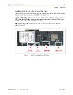
Page 52: ...il Card The Flash based Voice Mail Card consists of a printed circuit board It can be installed into Slot 7 in the Basic KSU Figure 3 10 Flash Based Voice Mail Card Memory Expansion Module Refer to Fi...

Page 53: ...o Slot 7 of the Basic KSU Equipment Handling Take every precaution to prevent static charges and physical strain from being applied to the STSe card When connecting this device power off the KSU and b...

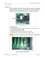
Page 54: ...BKSU Refer to Figure 3 12 MODU Installation Location Installing the MODU 1 Using a grounding strap unpack the MODU from its antistatic bag in the packing box 2 Locate the MODU connector on the MBU 3 L...

Page 55: ...new EPROMs Refer to Figure 3 13 for an illustration of the proper location for the EPROMs The processor board has silkscreen U2 and U3 labels to identify the proper mounting points To properly orient...

Page 56: ...IB slot slot 3 the single line ports will be numbered 108 111 Ports 148 and 149 are always for the two built in single line ports Caremustbetakenwhen wiringstations toensurethatdigitalkeysetsareonlywi...

Page 57: ...L BK 111 135 12 37 12 BK OR OR BK 112 136 13 38 13 BK GN GN BK 113 137 14 39 14 BK BN BN BK 114 138 15 40 15 BK SL SL BK 115 139 16 41 16 YL BL BL YL 116 140 17 42 17 YL OR OR YL 117 141 18 43 18 YL G...

Page 58: ...20 8 33 8 RD GN GN RD 9 21 9 34 9 RD BN BN RD 10 22 10 35 10 RD SL SL RD 11 23 11 36 11 BK BL BL BK 12 24 12 37 12 BK OR OR BK 13 38 13 BK GN GN BK Blank 14 39 14 BK BN BN BK Blank 15 40 15 BK SL SL...

Page 59: ...B pairs 1 8 Station Champ Stations 100 107 1 Built In LCI4 pairs 1 4 CO Champ COs 1 4 2 Built In SLIB2 modular plugs Stations 148 149 3 Open 4 DTIB pairs 17 25 Station Champ Stations 108 115 5 Open 6...

Page 60: ...og Device Port ADP jack The ADP jack is an open twisted pair conductor path that may be extended from the KSU via the second pair of the station cabling The ADP jack may be used to extend an SLT stati...

Page 61: ...urce may cause the distances to vary The distance between the KSU and the DTIBL should always be greater than the distance between the DTIBL and the keyset It is recommended that the DTIBL only be use...

Page 62: ...telephone unit KTU 2 Connect the 6 wire line cord from the right plug on the base of the KTU to the plug labeled KTU on the CTI module 3 Connect the 9 pin 3 wire straight through serial cable from the...

Page 63: ...th the digital DTIB and analog SLT interfaces Refer to the Single Line Adapter s Installation Guide that is provided with the SLA for additional information Figure 3 15 SLA Single Line Adapter Single...

Page 64: ...e handset secure during use in a wall mount configuration 4 Turn telephone over and unplug the line cord 5 Run the line cord through the rectangular hole of the Wall Mount and plug into connector on t...

Page 65: ...he 2 5mm connector on the left side of the keyset or 1 Remove the handset cord from the bottom of the Key Telephone unit 2 Plug the Headset Adapter cord into the vacant handset jack on the Key Telepho...

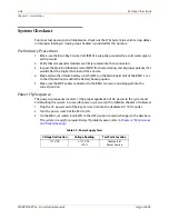
Page 66: ...witch SW4 on the Main Board Unit of the BKSU is set to the ON position to enable the battery backup option 5 Make sure the MDF cables connected to the BKSU are secure and plugged into the correct posi...

Page 67: ...with the Call Box Alternatively the unit can be mounted beyond the reach of visitors and wired to a conventional doorbell switch which then serves as the Call Button This option helps protect the Doo...

Page 68: ...3 40 Door Box Chapter 3 Installation STARPLUS STSe Installation Manual August 2005...
Page 69: ...ter provides a guideline for isolating and resolving functional problems that may be encountered due to improper use or component failure of the STARPLUS STSe system Other failures such as no dial ton...

Page 70: ...N O T E S...

Page 71: ...priority Then make the necessary programming changes incustomer database programming to acquire the desired operation If feature operation is not the cause of the suspected problem then general troubl...

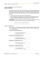
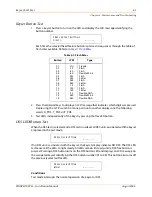
Page 72: ...up the Test Mode Menu on the keyset s LCD To exit the test mode place the handset back on hook This reconnects the keyset to the system Test Mode Menu The menu allows you to select a test mode by dia...

Page 73: ...ted and a DSStest is invoked all DSS unitsassociated with thekeyset are placed in the test mode If no DSS unit is associated with the keyset the keyset display indicates NO DSS The DSS LED test causes...

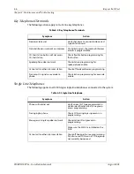
Page 74: ...heck flexible button programming for that button Speakerphone does not work Check station programming for speakerphone enable Cannot call another intercom station Check off hook preference programming...

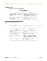
Page 75: ...on identification assignment in programming for correct DSS map assignment Pressing buttons on DSS does not activate keyset DSS must be assigned to keyset in station ID programming Table 4 5 CO Line L...

Page 76: ...correctly activated feature does not work properly Check system programming related to specific feature Loss of system intercom dial tone and call processing tones Check off hook preferences headset m...

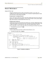
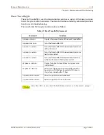
Page 77: ...theRS232 1port COM1 of the BKSU or connected to the modem After the prompt displays enter the password thenpress Enter Properentryofthepassworddisplaysthemaintenanceprompt The Maintenance password is...

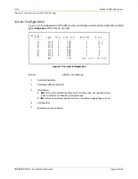
Page 78: ...lot position 2 Card type of that card slot 3 Card status OOS status can indicate the entire card is out of service or a specific station is not installed or installed but not operational INS status ca...

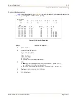
Page 79: ...Waiting 3 Status OOS status can indicate the entire card is out of service a specific station is not installed or installed but not operational INS status can indicate a specific station is installed...

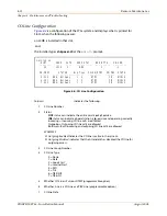
Page 80: ...ncoming CO line calls are allowed Outgoing Outgoing CO line calls are allowed Bothway Both incoming and outgoing CO line calls are allowed EXAMPLES Outgoing Enabled indicates the CO line is active in...

Page 81: ...urn Turns the Trace buffer OFF t space 1 return Turns the Trace buffer ON to record events prior to a soft system reset t space 2 return Turns the Trace buffer ON to record events prior to a hard syst...

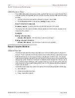
Page 82: ...ake busy Making a Receiver Available d space rXX return XX is the receiver number to make available Remote System Monitor General Overview The Remote System Monitor feature provides access to the inst...

Page 83: ...cture s s Dump Station memory structure d a a Dump a memory address structure The data obtained from these commands is in hexadecimal format and is used primarily for manufacturer level support The Re...

Page 84: ...the trace desired or type all when all boards CO lines or Stations events are desired 001 028 CO Line port 100 149 Station location All All Boards CO lines or Stations B Board event trace traces even...

Page 85: ...begins as shown in Figure 4 8 Modify Memory Command The Modify Memory command is for engineering use only Unless instructed by personnel at Vodavi Technical Support do not leave the trace mode enabled...

Page 86: ...The standard format is 80 characters per line A 30 character format generates three lines per message mon x DATE MM DD YY TIME 10 46 33 exiting monitor Sta 100 State IDLE Evt Dial Pad 26 Data 1 Sta 10...

Page 87: ...23456789012345678901234567890 AAAA BBB HH MM SS HH MM MM DD YY HCCCCCCCCCCCCCCCCCCCCCCCC GGGGGGGGGGGG CR LF STA CO TOTAL START DATE DIALED 102 031 00 00 11 13 59 01 15 01 O2101 CALL TO STA2101 80 char...

Page 88: ...lash Bank erasure complete followed by the display To start XMODEM upload enter Yes y or No n 7 Type y for Yes You then receive a display Uploading file with xmodem 8 Use the Transfer dropdown menu an...

Page 89: ...orts with the on board LCOB Can the STSe support networking No The STSe does not support networking Does the STSe support a full or fractional T1 The STSe accommodates either a full or a fractional T1...

Page 90: ...tal keyset No Since the Wanderer is an extension of your keyset it does not require the use of an additional digital port on the DTIB Are my DHS phones compatible with the STSe No DHS phones are not c...

Page 91: ...34 Configuration Tables 2 3 CTI Module 3 34 D Dialed Number ID Service DNIS 3 18 Dialing Specifications 2 7 Digital Keyset Wall Mounting 3 36 Digital Keyset Terminal Wiring 3 32 Digital Loop Extender...

Page 92: ...Up Sequence 3 38 PRIB 1 8 3 21 Primary Rate Interface Board 1 8 3 21 Program Module Unit 3 12 R Remote Maintenance 4 9 Remote System Monitor 4 14 S Single Line Adapter 3 35 Single Line Telephone Inter...

Page 93: ...ications 2 4 CO Line Buttons 2 4 DSS BLF Buttons 2 5 Feature Function Buttons 2 5 VMIB 3 24 3 25 Voice Mail Interface Boards Flash based Voice Mail Card 3 24 Hard Drive based Voice Mail Card 3 24 W Wa...

Page 94: ...iv Index STARPLUS STSe Installation Manual August 2005...
Reviews: