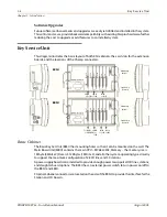
1-6
Extension Boards
Chapter 1 - Introduction
STARPLUS STSe - Installation Manual
August 2005
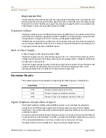
Ring Generator Unit
The Ring Generator Unit (RGU) provides the ring voltage to the SLIB circuits to ring the SLT. The
RGU also provides the input to the Message Wait source on the SLIB cards. The output of the
RGU is 65V AC, 25 Hz. The RGU can support simultaneous ringing for all SLTs associated to the
SLIB. The RGU is built-into the SLIB2 and into the SLIB4.
Expansion Cabinet
The Expansion Key Service Unit (EKSU) mounts above the BKSU and is connected via cables that
extend the voice and data signaling to and from the BKSU. An integral power supply provides
enough power to support all CO lines, stations, and daughter board options.
The EKSU has mounting holes so that it can be mounted on the wall. The station connections
are via a 50-pin amphenol connector. This connector is located in the EKSU. CO connections are
50-pin type and are located on the EKSU board.
Built-in Power Supply
A Power Supply is built into each cabinet’s MBU.
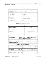
The Power Supply converts commercial AC power (105 / 117 / 129 V AC @ 47-63 Hz) to ±5V DC
voltage output, regulates the voltage, and provides the appropriate DC voltage for distribution
to other system components.
The Power Supply includes circuitry to charge two externally-connected 12-volt batteries and
controls operation of the battery back-up circuits. The Power Supply provides system
operating voltages from the batteries if commercial AC power fails.
Extension Boards
These extension boards are capable of supporting the following types of telephones:
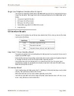
Digital Telephone Interface Board (8 port)
The Digital Telephone Interface Board (DTIB) provides 2-wire interfaces for telephone
connection. The DTIB provides digital voice and data communications to/from digital
telephones. This card provides eight standard Digital Telephone Interface circuits and installs
in the BKSU or EKSU.
An industry-standard amphenol-type female connector is mounted on the side of the KSU for
connection to the station interfaces. One LED is mounted on the PCB to indicate the in use state
of the connected telephones. It will turn on when one or more ports are busy.
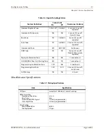
The digital station circuit specifications: One-pair wiring to digital devices
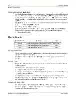
Board Name
Function
DTIB
Provides 8 Digital Telephone interfaces
SLIB4
Provides 4 Single Line Telephone interfaces
SLIBC
Provides 4 Single Line Telephone interfaces & Caller ID
Summary of Contents for STSe Key System
Page 1: ...August 2005 Issue 1 0 STARPLUS STSe Key Systems Installation Manual TM...
Page 4: ......
Page 10: ...vi Figures STARPLUS STSe Installation Manual August 2005...
Page 12: ...viii Tables STARPLUS STSe Installation Manual August 2005...
Page 14: ...N O T E S...
Page 22: ...N O T E S...
Page 30: ...N O T E S...
Page 68: ...3 40 Door Box Chapter 3 Installation STARPLUS STSe Installation Manual August 2005...
Page 70: ...N O T E S...
Page 94: ...iv Index STARPLUS STSe Installation Manual August 2005...


