– 31 –
Appendix C: Optional Ethernet Interface IFBD-HE05
<Initializing Settings>
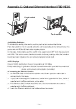
To initialize the setting information, set the push switch as described below.
Push the switch for 1 to 5 seconds while the unit is operating in the normal mode. The
green and red LEDs will flash with a regular pattern.
In this state, momentarily push the switch once again to turn OFF both the green and
red LEDs. This will revert the interface board to its factory settings. After the interface
board has been initialized, the unit will automatically reboot itself.
<LED Display>
Green (100M): Lights when the port is operating at 100 Mbps.
Red (Link/Activity): Lights when the link is made between the port and the connected
device, and mutual communication is enabled.
<Connecting the Ethernet Cable>
1. An Ethernet cable is not included with the unit. Please provide a cable that is
appropriate for the specs.
2. To prevent electromagnetic interference, attach the supplied ferrite core, which is
supplied with the Ethernet board, to the cable.
3. For details on how to attach the ferrite core, see the installation sheet that is
supplied with the Ethernet board.
4. Insert the Ethernet cable into the interface board connector.
Push switch
LED
Push switch
Summary of Contents for TCP400 SERIES
Page 1: ...THERMAL RE WRITABLE CARD READER WRITER TCP400 SERIES User s Manual...
Page 13: ...1 11 2 13 3 13 4 14 5 15 6 16 7 16 8 18 28...
Page 14: ...11 1 1 1 1 2 3 4 5 6 7 8 9 1 2 1 Star 2 3 4 5 6 7...
Page 15: ...12 8 9 10 11 12 13 14 15 16 17 18 19 20 21 22 23...
Page 16: ...13 2 1 2 3 4 5 6 3 6 5 4 3 7 2 1 1 2 3 4 5 6 7...
Page 17: ...14 4 RS 232C USB 4 1 RS 232C 1 2 3 4 4 2 USB 1 USB 2 USB USB 3 USB USB 4...
Page 18: ...15 5 1 2 3...
Page 19: ...16 6 1 2 3 4 COMPLETE 7 7 1 85 6 89 6 22 0 54 0...
Page 20: ...17 7 2 1 300 2 3 300 7 3 1 2 3 4 1 2 85 3 4 85 5 30...
Page 21: ...18 8 8 1 8 2...
Page 22: ...19 8 3 1 2 3 4 5 6 7...
Page 23: ...1 21 2 22 3 23 4 23 5 24 6 24 7 25 8 26 28 KOREAN...
Page 24: ...21 21 1 1 1 1 2 3 4 5 6 7 8 9 1 2 1 2 3 TV 4 5 6 7 8 9 10 11 12 13 14 15...
Page 25: ...22 16 17 18 19 20 21 22 23 DC 2 1 4 2 5 3 2 6...
Page 26: ...23 3 6 5 4 3 7 2 1 1 2 3 4 5 6 AC 7 4 RS 232C USB 4 1 RS 232C 1 2 3 4 4 2 USB 1 2 USB 3 4...
Page 27: ...24 5 1 2 AC 3 AC 6 1 2 3 4 COMPLETE...
Page 28: ...25 7 7 1 7 2 1 300 2 3 300 LED 7 3 1 2 3 4 1 2 85 3 4 85 5 30 85 6 89 6 22 0 54 0...
Page 29: ...26 8 8 1 LED 8 2...
Page 30: ...27 8 3 1 2 3 4 5 6 7...

