background image

2.4 

Connect Wiring Harness to ECO Pro

2.4.1  Locate connector on back of   


ECO Pro face plate. 

2.4.2  Refer to Figure 3 and plug 


wiring harness from MC521    


Pro to ECO Pro connector.

Figure 3. Connect Wiring Harness to ECO Pro

3.1 

Power on MC521 Pro Controller

3.  Configure ECO Pro - Service Menu

Figure 4.  Attach ECO Pro Face Plate

2.5 

Verify Power to ECO Pro

2.5.1  Turn on the MC521 Pro  


Controller and verify the ECO  


Pro is receiving power.

Note:

Screen will read “Closed Locked”

2.5.2  Turn off power.

2.6 

Attach ECO Pro Face Plate

2.6.1  Refer to Figure 4. Using the #6- 


20 X 5/8” screws provided,    


attach ECO Pro face plate to    


mounting plate.

2.6.2  Feed unused wiring length into 


the jamb; use best practices to 


avoid causing damage to  


harness.

2.7 

Set Date and Time

2.7.1  Power on MC521 Pro Controller.

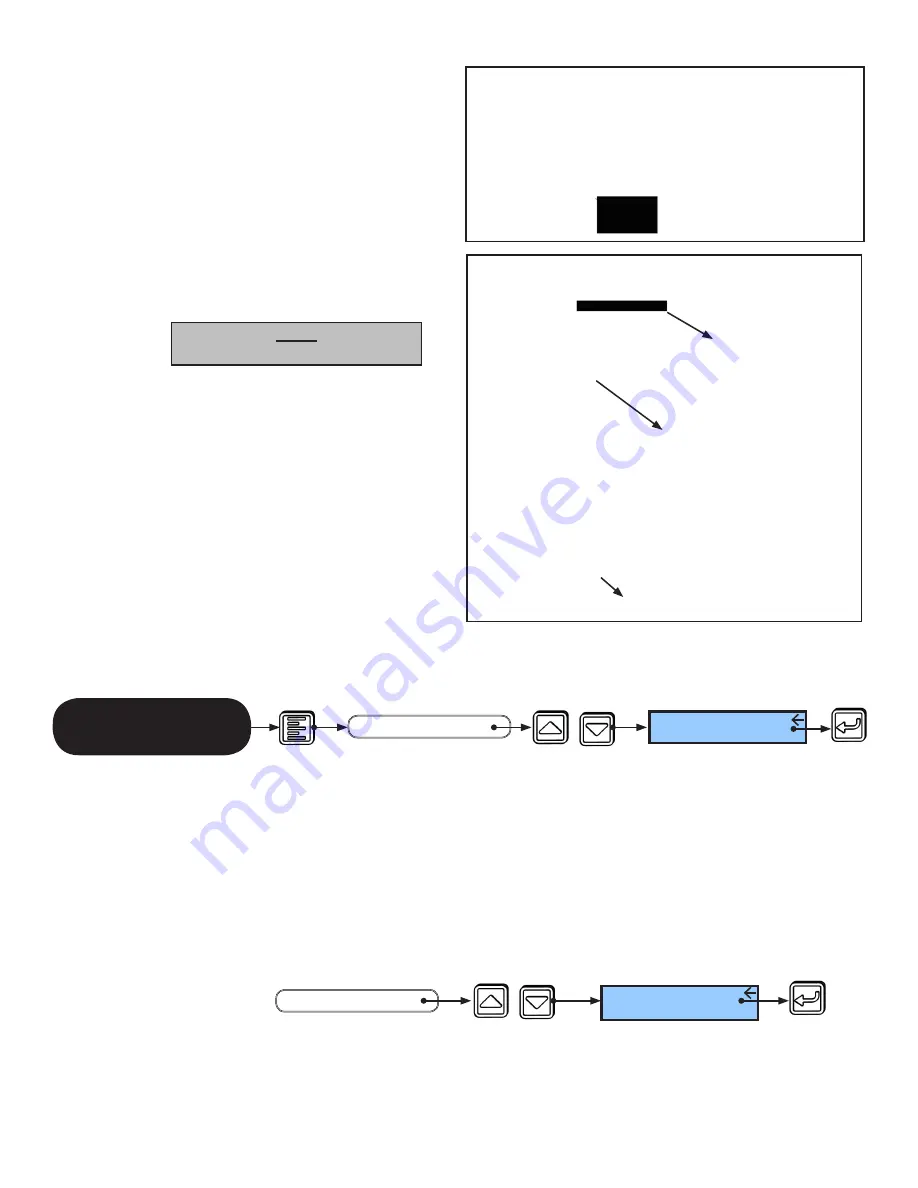
2.7.2  From the ECO Pro Home Screen, Press the Menu button, then arrow to “Set Date &  


Time” and press “Select.”

2.7.3  Follow the prompts on the LCD Screen.

PRESS 

PRESS 

Set Date & Time


START

Home

Screen

MAIN MENU

SEE 

3.2    Access the Service Menu

3.2.1    From the Main Menu, arrow to highlight “Service Functions” and press “Select.”

Service Functions


MAIN MENU

START

SEE 

PRESS 

PRESS 

204082

Rev. B 10/11/2012

Page 2 of 12

PRESS 

Top View Shown

© 2012, STANLEY BLACK & DECKER. ALL RIGHTS RESERVED.

Summary of Contents for ECO Pro

Page 1: ...ounting Plate 2 3 1 Determine customer preferred orientation of mounting plate Refer to Figures 2a 2b for orientation options 2 3 2 If necessary use Mounting Plate as a template Refer to Attachment 2...

Page 2: ...cked 2 5 2 Turn off power 2 6 Attach ECO Pro Face Plate 2 6 1 Refer to Figure 4 Using the 6 20 X 5 8 screws provided attach ECO Pro face plate to mounting plate 2 6 2 Feed unused wiring length into th...

Page 3: ...act 3 2 2 Enter the key sequence as follows Hold Menu button 1 and Press Down Arrow 2 and RELEASE both buttons Then hold Select 3 and Press Up Arrow 4 and RELEASE both buttons Note 1 This is a menu in...

Page 4: ...ally saved to memory PRESS PRESS SEE Door ID ANNNNN END 3 3 1 From the Service Menu arrow to MC521 Control and press Select 3 3 2 Arrow up to Function Sw Software and press Select to save 3 3 Enable E...

Page 5: ...UCED Start Up Mode REDUCED ONEWAY 4 or 6 Position Switch Only 6 Position Switch Only END OR OR OR OR Start Up Mode CLOSED OR 3 7 Change Support Contact Information if necessary 3 4 1 From Service Menu...

Page 6: ...ss Select to save 4 3 1 Set Closed Mode Closed Mode programs the door operating mode to enable Oneway once Closed Locked is selected The door operating mode switches to proper Closed Locked once the d...

Page 7: ...the Function Menu arrow to Traffic Sense and press Select Arrow to either Enabled or Disabled and press Select to save 4 3 2 Set Hold Open Mode Hold Open Mode allows for ECO Pro to use two different...

Page 8: ...ess hole and the mounting holes for the screws 3 Mark punch the mounting screw locations 4 Cut a 1 250 hole using a hole saw 5 Using a 26 drill bit 147 dia drill the 2 holes for the mounting screws No...

Page 9: ...3 2 9 Set Traffic Sense Option Default Traffic Sense is Off 4 3 3 10 Perform ECO Pro Closeout Procedure 5 ECO Pro Service Checklist Step Action Reference Section Complete 1 Review Error History From M...

Page 10: ...be used with access control systems by connecting the activation output of the access control system to the hold open input of the MC521 Pro TB2 1 to TB2 2 In this way the ECO Pro can automatically s...

Page 11: ...T indicates the door is functioning properly A flashing RED LIGHT indicates the door is not functioning properly The LCD HOME SCREEN displays the operating mode alerts instructions to correct alerts a...

Page 12: ...This page left intentionally blank 204082 Rev B 10 11 2012 Page 12 of 12 2012 STANLEY BLACK DECKER ALL RIGHTS RESERVED...

Reviews: