6
LOCATION
Prior to installation, ensure that the local distribution
conditions (nature of the gas and gas pressure) and
adjustment conditions are compatible. The
adjustment conditions for this appliance are stated
on the data badge which is fitted inside the bottom
burner door.
When choosing a location for this appliance you
must have:
(a) S u fficient room for the installation (see
clearances), a satisfactory flue, and an
adequate air supply for correct combustion and
operation. (See Ventilation & Combustion Air
Requirements).
(b) Adequate space for maintenance and air
circulation.
(c)
Solid floor or base of non-combustible material
which is capable of supporting the total weight
of the appliance. (see Technical Data).
ELECTRICAL SUPPLY
All wiring external to the appliance must conform to
the current BS 7671, B.S. 7462, Safety Document
635, ETC: Part 1 section 5.4.6. & The Electricity at
Work Regulations. The cooker requires a 230V -
240V, 50Hz supply. Connection of the appliance
and any system controls to the mains supply must
be through a moulded on plug top, (with a 5?Amp
fuse fitted), which is fitted to the appliance in
accordance with EN 60335, Consumer Protection, -
S.I. 1994 No. 1768, plug and sockets etc. (safety)
Regulations 1994.
Always install in accordance with current local
wiring regulations.
WA R N I N G : THIS SUPPLY AND APPLIANCE
MUST BE EARTHED
(Refer to B.S. 7430 Code
of Practice for Earthing)
Where a risk of low voltage can occur, a voltage
sensitive device should be fitted to prevent start up
of the burner so as not to endanger the installation.
(see fig. 30)
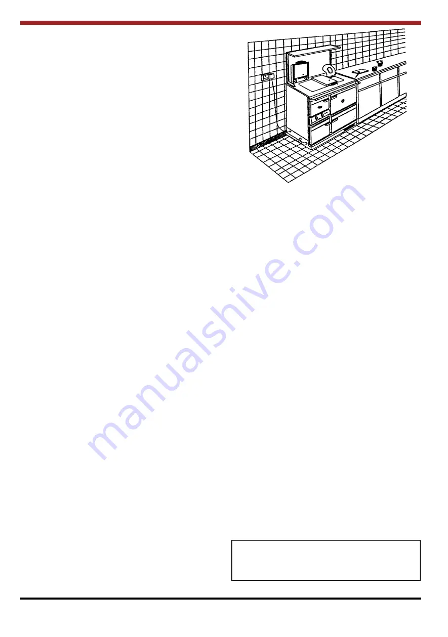
To isolate the appliance completely, unplug from the
mains socket. Always ensure that this socket is
easily accessible and close to the appliance.
Persons in charge of this appliance should be aware
of this socket outlet position.
GAS PIPES AND FITTINGS
Materials used for installation work should be fire
resistant and gas tight and should conform to the
following or their equivalent:
* B.S. 2871 Part 1 & pr EN 1057 - Copper Tubes.
* B.S. 219, EN 29453 & ISO 9453 - soft solders.
* B.S. 759 - Valves, gauges and other safety
equipment.
* B.S. 1387 - Steel tubes.
* B.S. 6362 & B.S. 4127 - Stainless steel tubes.
* B.S. 1552 - Manual Shut of valves.
* B.S. 1740 - Wrought steel pipes.
* B.S. 5295 & B.S. 6956 Jointing Materials.
* B.S. 4089 - LPG hoses and assemblies.
METERS
A suitable gas meter must be connected to the
service pipe either by a representative of the gas
board or by an appointed contractor. If using an
existing meter have it checked to ensure that the
meter is capable of dealing with the total rate of gas
supply needed. (See Technical Data).
GAS PIPE SIZE
It is important that the correct service pipe size be
used in order to ensure an adequate gas supply.
This depends on the distance between the supply
meter, the pressure drops caused by bends and the
expected pressure drop in the gas mains at peak
demand times.
NOTE: The Donard has an input rating of 24.9 kW
(85,300 Btu’s/hr) approximately. See BS 6891. (If
in doubt consult your gas supply company)
A
3/4
” gas shut off valve, which does not cause a
restriction in flow or a pressure drop when open,
must be fitted as close to the appliance as possible.
This tap should be accessible at all times.
Fig. 1
WARNING: To avoid pipe sealing compounds from
entering into the gas train, do not apply sealing
compound to the first two threads at the tip of the
gas connection.


