Manual/Automatic Depth Control
Manual/automatic depth control ensures an even depth of soil in the finished bed.
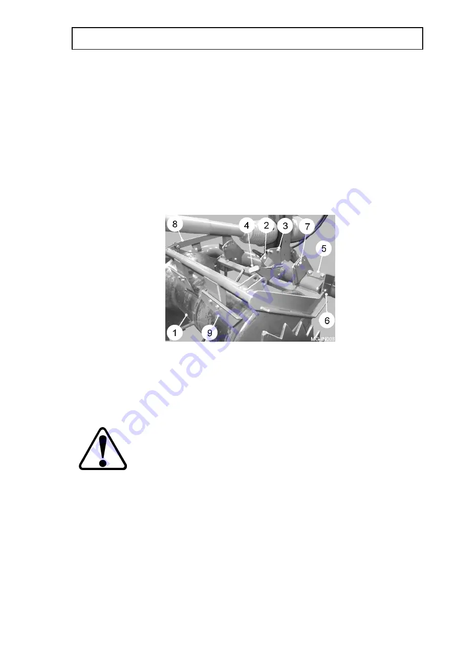
The depth roller (item 1, fig 8) runs on top of the preformed bed following the
contours. On machines with manual depth control a turnbuckle is fitted between the
chassis and depth roller frame. Adjusting the length of the turnbuckle effects the
digging depth of the shares. On machines with automatic depth control, the depth
roller is linked to a trigger plate (item 2, fig 8) which activates a pair of proximity
sensors (item 3, fig 8) which then, via the valve block, actuate the share depth ram.
Turning the adjuster handle (item 4, fig 8) changes the relationship between the
depth roller and the trigger plate thus adjusting the working depth. An optional linear
actuator can be fitted in place of the handle mechanism allowing adjustment from the
in-cab control box. A depth indicator (item 6, fig 1) is fitted to the share depth ram
giving the operator a visual indication of the action of the sensing system.
The depth roller frame pivots on two rubber torsion mountings (item 5, fig 8). By
adjusting these mountings it is possible to adjust the amount of pressure the roller
exerts on the soil. The adjustment is made with the machine raised out of work with
the roller hanging freely. Loosen the torsion mounting bolts (item 6, fig 8) and remove
the pressure setting bolts (item 7, fig 8) and raise the roller until the holes align with
the chosen hole setting and refit the bolts.
A transport strap (item 8, fig 8) is fitted between the depth roller frame
and the chassis. The strap must be removed before commencing work.
The scrapers (item 9, fig 8) are fitted to the to eliminate dirt build up on the roller. Set
the scrapers as close as possible to the roller surface but ensure they do not restrict
the roller from turning.
Discs
The discs (item 1, fig 9) cut and contain the soil while feeding it over the shares onto
the stars. Both discs should be adjusted so that the inner faces are approximately 5
mm from the outside edge of the share blades. To adjust the discs, slacken hub
clamp bolts (item 2, fig 9) and slide the disc to the required position. Retighten clamp
bolts.
OPERATION
1.14
Fig 8
Summary of Contents for MEGASTAR GEN-2
Page 2: ......
Page 4: ......
Page 10: ...1 5 SAFETY PRECAUTIONS ...
Page 11: ...SAFETY PRECAUTIONS 1 6 ...
Page 34: ...Input Drive Belt Adjustment 1 29 MAINTENANCE ...
Page 35: ...LH Drive Belt Adjustment MAINTENANCE 1 30 ...
Page 36: ...RH Drive Belt Adjustment 1 31 MAINTENANCE ...
Page 38: ......


