Istruzioni Instructions Betriebsanleitung
14
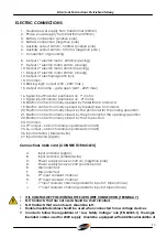
at least 1 mm, and should be at least 4 mm from those with low voltage.
•
The cables used for power supply of motors, should be of at least 2.5 mm
2
and the length
should not exceed 10 m;
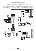
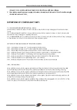
DEFINITIONS OF CONTROL UNIT PARTS
F1- FUSE TRANSFORMER INPUT(F10A, 250V):
protects the center in case of short circuits or faults that may emerge at the transformer
input.
F2 – FUSE AUXILIARY OUTPUT ( T1.6A, 250V): protects the center in case of short circuits and
faults that may emerge in auxiliary devices.
F3 – FUSE BLINKER (T1.6 A, 250V): protects in case of short circuits and faults that may emerge
in the blinker or in the control device of the opened gate.
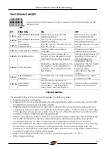
DIP SWITCH FOR SELECTION OF FUNCTION MODES:
SW – 1 indicates torque of 1
st
motor (electric friction M1).
SW – 2 indicates torque of 2
nd
motor (electric friction M2).
SW – 3 indicates the operational sequence of the command Open/Close.
SW – 4 allows the set up of the function mode for automatic o semiautomatic.
SW – 5 allows the insertion “ battering ram” during the opening phase.
SW – 6 allows selection of delaying the second in respect to the first shutter.
SW – 7 allows selection of operating with 1 or 2 motors.
SW – 8 allows adjustment of the mains for automatic cycle and intervals.
LED – SIGNALLING:
DL2 – (RED): a Led which signals activation of the photocell in the closed mode; the LED
automatically switches off when the photocell detects an obstruction during closing.
DL3 – (RED): a Led which signals activation of the photocell in the opened mode; the LED
automatically switches off when the photocell detects an obstruction.
DL4 – (RED): a Led which signals blockade of the gate; the LED automatically switches off
when the command Stop is activated.
DL5 – (RED): a Led which signals whether the central unit is plugged( on) or not( off); in the
case of supply from the accumulator the LED switches off.


