


Bill of materials
UM0432
48/53
33
J5
Vbus-2-WAY screw terminal
Through hole
34
J6
+10 V
Through hole
35
J10
Phase OUT-3-WAY screw terminal
Through hole
36
J14
5-pin strip-line male
Through hole
37
J22,J27
1-pin strip-line male
Through hole
38
J23,J24
3-pin strip-line male
Through hole
39
L1
470 µH 0.35 A
SMD
40
L3
15 µH 1 A
SMD 1210
41
NTC1
10 k
Ω
SMD 0603
42
R12,R13,R19,R64,R68,
R72,R73,R75
10 k
Ω
- 1/4 W
SMD 1206
43
P1,P2,P3
50 k
Ω
- trimmer
Through hole
44
P4
100 k
Ω
- trimmer
Through hole
45
R20
100 k
Ω
- 1/4 W
SMD 1206
46
Q8
STMicroelectronics STN4NF03L
SMD
47
Q9,Q10,Q11,Q12,Q13,Q14,
Q15,Q16,Q17,Q18,Q19,Q20
(NC)
SMD
48
RF1,RF2,RF3
330 k
Ω
- 1/4 W
SMD 1206
49
R1,R4,
680
Ω
- 1/4 W
SMD 1206
50
R1,R50,R63,R71
470 - 1/4 W
SMD 1206
51
R2
100 k
Ω
- 1/4 W (NC)
SMD 1206
52
R3,R5,R6
10 k
Ω
- 1/4 W (NC)
SMD 1206
53
R7,R8,R17,R18,R67
4 7 k
Ω
- 1/4 W
SMD 1206
54
R9,R10,R11
(NC)
SMD 1206
55
R14
100
Ω
- 1/4 W
SMD 1206
56
R15
1 M
Ω
- 1/4 W
SMD 1206
57
R16
1.2 k
Ω
- 1/4 W
SMD 1206
58
R21
33 k
Ω
- 1/4 W
SMD 1206
59
R26
470
Ω
- 1/4 W
SMD 1206
60
R27,R41,R53,R65
15 k
Ω
- 1/4 W
SMD 1206
61
R28
4.6 k
Ω
- 1/4 W
SMD 1206
62
R29
18 k
Ω
- 1/4 W
SMD 1206
63
R30
3.3 k
Ω
- 1/4 W
SMD 1206
64
R31,R45,R57
200
Ω
- 1/4 W
SMD 1206
65
R32,R47,R59,R69
22 k
Ω
- 1/4 W
SMD 1206
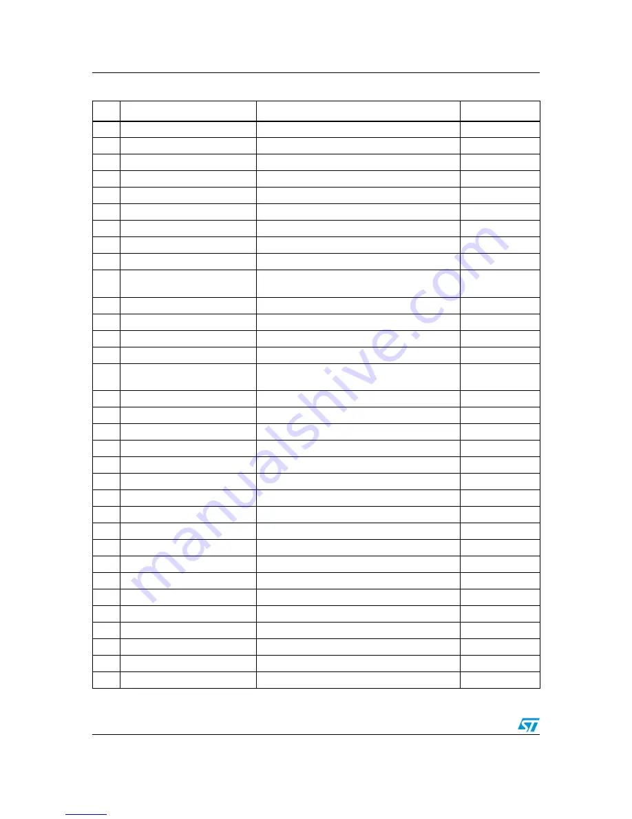
Table 23.
Bill of materials (continued)
Item
Reference
Part
Footprint
electronic components distributor