


Motor control operations
UM0432
42/53
Also change the following define in the
mtc.h
file:
#define mem_MCRC_GE ((u8)71)
7.6
Driving the BLDC motor (trapezoidal - sensored)
This section describes how to drive the brushless permanent magnet motor with three hall
60° sensors. First you should check that the board has been set-up for BLDC 60° sensor
driving (see
Section 7.4.4
).
7.6.1 Specific
sensor connections
In order to be driven correctly, the motor must have three position sensors, in this case three
hall sensors. For this demonstration, we suggest using one Ametek BLDC blower motor
(voltage max 30 Vdc).
Use the connections described in
Table 17
to connect the motor to the power board.
7.6.2
Specific jumper settings
Set-up the board following the instructions in
Section 7.4.12
(bus voltage between 9 and 28
V) and
Section 7.4.13
.
Set-up the board as per
Table 18
.
7.6.3
LED action after power-on
Turn on the power supply. For this demonstration, the power supply output voltage should be
set to 20 Vdc and the current limitation of the power supply should be set to 4 A.
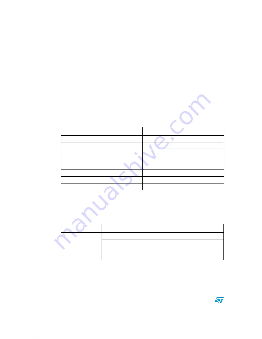
Table 17.
"BLDC sensored" motor connections
Motor
Power board
Phase A (red)
J10 pin 1
Phase B (yellow)
J10 pin 2
Phase C (black)
J10 pin 3
Hall sensor 1 (white)
J14 pin 1
Hall sensor 2 (green)
J14 pin 2
Hall sensor 3 (blue)
J14 pin 3
Hall 5V (red)
J14 pin 4
Hall ground (black)
J14 pin 5
Table 18.
BLDC SR jumper settings
Driving mode
Jumper settings
BLDC_3PH_SR
J11 open, J12 open, J13 between 2-3
J15 open, J16 open, J17 between 2-3
J18 open, J19 open, J20 between 2-3
J3 closed, J4 variable (2-3)
electronic components distributor