EN - 10
Write the identification data of the
machine in the specific space on the
label on the back of the cover page.
ATTENTION
State the identification data on the product
identification label whenever you contact
an Authorised Service Centre.
NOTE
An example of the Declaration of Conformity
is provided on the last pages of this manual.
3.4 MAIN COMPONENTS
The machine is composed of a series
of main components that have the
following functions (Fig.1 ):
A. Engine
: drives cutting means motion via
transmission shaft and angle transmission.
B. Rod
: it connects the rear hand
grip to the power unit.
C. Angle transmission:
final part of
the transmission tube that transmits
motion to the cutting means.
D. Cutting means
: the element
designed to cut vegetation
1. Cutting line head
: nylon
line cutting means.
2. Blade:
metal disc cutting
means (in the box).
E. Cutting means guard
: it is a safety
device which prevents objects drawn
up by the cutting means from being
hurled away from the machine.
F. Handle bar:
"cow horn" handle bar placed
transversely to the rod and asymmetrically to
it; used to control the machine; the main on/
off commands are located on the right side.
G. Machine support
: a piece which, when
attached to the battery backpack, helps
supporting the machine during operation.
H. Connection point:
point in which the
machine is attached to the battery backpack.
I. Blade protection
(for machine
transport and handling): protects against
accidental contact with the cutting
means that can cause serious injuries.
J.
Battery backpack
(attachment
on request, par. 15.3): device in
which the batteries are placed.
K. Battery
: (attachment on request. 15.1)
device that supplies electric power to the tool.
L. Battery charger
(accessory available
upon request, paragraph 15.2)
: device
used to recharge the battery. Three battery
charger models are available:
L1
(fast
battery charge);
L2
(standard battery
charge),
L3
(dual battery charge).
M. Connection cable:
cable used to connect
the machine to the battery backpack.
4. ASSEMBLY
DANGER
The safety regulations to be followed are
described in chapter 2. Strictly comply with these
instructions to avoid serious risks or hazards.
For storage and transport purposes, some
components of the machine are not installed
in the factory and have to be assembled after
unpacking. Follow the instructions below.
ATTENTION
Unpacking and completing the assembly
should be done on a flat and stable surface,
with enough space for moving the machine
and its packaging, always making use of
suitable equipment. Do not use the machine
until all the instructions provided in the
“ASSEMBLY” section have been carried out.
4.1 ASSEMBLY COMPONENTS
The packaging includes assembly components.
4.1.1 Unpacking
1.
Carefully open the packaging, paying
attention not to lose components.
2.
Consult the documentation in the
box, including these instructions.
3.
Remove all the unassembled
parts from the box.
4.
Remove the machine from the box.
5.
Dispose of the box and packaging in
compliance with local regulations.
DANGER
Before assembly, check that the machine is
not connected to the battery backpack.
4.2 FITTING THE HANDLE BAR
1.
Fit the handle (Fig. 3.A) in its seat
on the handlebar (Fig. 3.B).
2.
Tighten the handle with the screw (Fig. 3.C).
3.
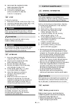
Insert the spring on the handlebar
support (Fig. 4.A).
Summary of Contents for BC 900 D Li 48
Page 5: ...1 XX XX XX XX XX C A C B 3 A B 4 5 6 A D C B 7 8 A C B B D C A ...
Page 6: ...1 XX XX XX XX XX 9 10 11 12 13 14 C D B B A B A C A B C A C B D E A ...
Page 7: ...1 XX XX XX XX XX 2 1 3 15 16 17 18 19 20 ...
Page 8: ...21 23 25 26 22 24 A B A B A B A ...
Page 9: ...A C D B 27 28 A B A B C D A B 150 mm 6 in 150 mm 6 in B A B C 29 28 27 ...
Page 44: ...ST S p A Via del Lavoro 6 31033 Castelfranco Veneto TV ITALY dB LWA Type s n Art N ...

