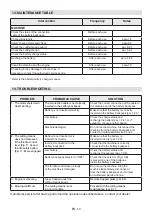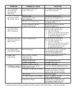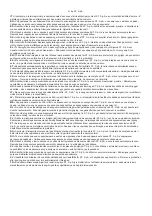
EN - 13
that the machine can be quickly released
from the straps in case of danger.
The machine support must be put on before
connecting the machine to the specific coupling
and the belt must be adjusted according
to the height and build of the operator.
•
Fasten the clip (Fig. 12.D) to the
specific coupling located on the
command rod (Fig. 1.H).
•
If necessary, disengage the quick
release (Fig. 12.C) to detach the
harness from the machine.
6.2 SAFETY CHECKS
Run the following safety checks and
ensure that the results correspond
to those outlined in the tables.
DANGER
Always carry out the safety checks before
use. If any of the results fail to match the
indications provided in the tables below, do not
use the machine! Take it to a service centre
to be checked and repaired if necessary.
6.2.1 General check
Object
Result
Hand grips (Fig. 1.F).
Clean, dry and fixed
firmly to the machine.
Cutting means
guard (Fig. 1.E).
Correctly and securely fit
to the machine, not worn/
deteriorated or damaged.
Connection point
of the machine
support (Fig. 1.H).
Correctly positioned.
Screws on the machine
and the cutting means.
Correctly tightened
(not loose).
Cutting means (Fig.
1.D.1; Fig. 1.D.2).
Clean, not damaged
or worn.
Metal blade (if fitted)
(Fig. 1.D.2).
Sharp.
Battery (Fig. 1.K)
No damage to the casing,
no liquid leakage.
Cooling air
ducts
(paragraph 7.3)
.
Not clogged.
Machine.
No signs of damage
or wear.
Connection cable of
the battery backpack
(Fig. 1.M).
No signs of damage.
Throttle control lever
(Fig. 11.A), throttle safety
button (Fig. 11.B).
The levers must move
freely and not be forced.
Test operation.
No abnormal vibrations.
No abnormal sound.
6.2.2 Machine operating test
Action
Result
1.
Insert the battery
in one of the
compartments of the
battery backpack
(par. 7.2.3 ).
2. Use the connection
cable to connect the
machine to the battery
backpack (Fig. 13 ).
3. Select the battery
using the selector
(Fig. 10.B)
.
The cutting means
must not move.
Operate the throttle
control lever (Fig. 11.A)
(without pressing the
throttle safety button).
The throttle control lever
remains blocked.
Operate the throttle
control lever (Fig. 11.A)
and the throttle safety
button (Fig. 11.B).
The throttle control
lever must move freely
and not be forced. The
cutting means moves.
Release the throttle
control lever
(Fig. 11.A)
and throttle safety
button
(Fig. 11.B).
The levers and the
button should return
automatically and
rapidly to the neutral
position and the cutting
means should stop.
6.3
START-UP
1.
Remove the blade guard (Fig. 1.J) (if fitted);
2.
adopt a firm and well-balanced position;
3.
Make sure the cutting means is not
touching the ground or any other object;
4.
use the connection cable to connect the
machine to the battery backpack (Fig. 13 );
5.
select the battery using the
selector (Fig. 10.B);
6.
operate the throttle control lever (Fig.
11.A) and the throttle safety button
(Fig. 11.B) at the same time.
6.4 OPERATION
Before starting any tasks for the first time, is
it recommended to get to know the machine,
learn the most suitable cutting techniques,
make sure you are wearing the harness
correctly, hold the machine firmly and perform
the movements required by the job.
Summary of Contents for BC 900 D Li 48
Page 5: ...1 XX XX XX XX XX C A C B 3 A B 4 5 6 A D C B 7 8 A C B B D C A ...
Page 6: ...1 XX XX XX XX XX 9 10 11 12 13 14 C D B B A B A C A B C A C B D E A ...
Page 7: ...1 XX XX XX XX XX 2 1 3 15 16 17 18 19 20 ...
Page 8: ...21 23 25 26 22 24 A B A B A B A ...
Page 9: ...A C D B 27 28 A B A B C D A B 150 mm 6 in 150 mm 6 in B A B C 29 28 27 ...
Page 44: ...ST S p A Via del Lavoro 6 31033 Castelfranco Veneto TV ITALY dB LWA Type s n Art N ...


