User Manual
CANopen/PROFIBUS DP Gateway
GT200-DP-CO
WWW.SSTCOMM.COM
60
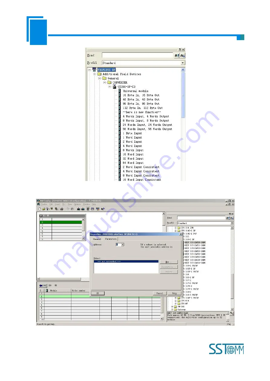
Figure 6
7. Set PLC rack, click the "Hardware Catalog \ SIMATIC 300 \ RACK-300 \ Rail"; Figure 7:
Figure 7
8. Set CPU module and select the corresponding device type and the occupied slots.


