background image


 3-2 

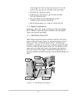
SELF-FLUSH 

Connect wash solution inlet and 
outlet tubing 
(opaque) to the flush housing as 

shown. 

Make sure ferrule is in the correct 
position. 


Screw syringe on luer fitting.  
Insert wash outlet tubing end 
into clear adapter. 


PUMP 

Connect pump inlet tubing as 
shown. 

Make sure ferrule is in the 
correct  
position. 


Ensure inlet line filter is 
submersed into solvent.   

Attach syringe to Prime-Purge 
valve.     

Open Prime-Purge valve by 
turning knob counterclockwise 
two turns. 

Draw syringe back to prime.  
Draw on syringe until no 
bubbles are seen

Summary of Contents for BINARY SOLVENT DELIVERY MODULE

Page 1: ...Binary Solvent Delivery Module Dual Series III Pumps with Serial PC and Voltage Control Operator s Manual 90 2581 rev B Scientific Systems Inc 349 N Science Park Road State College P 16803...

Page 2: ......
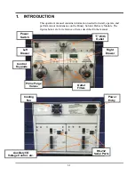
Page 3: ...maintenance on the Binary Solvent Delivery Module The figures below are for reference of items described in the manual Left Drawer Right Drawer Control Keypads Outlet Filters Prime Purge Valves T With...

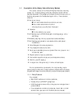
Page 4: ...ded seal life and reduced maintenance f Pulse Dampener for reduced pulsation f Very high performance price ratio f Easily user adjustable process set points flow rate pressure etc via front key pads f...

Page 5: ...piston 1 1 3 Self Flushing Pump Head Self flushing pump heads provide continuous washing of the piston surface without the inconvenience of a manual flush or gravity feed arrangement The self flushing...

Page 6: ...Flush then crystals will form with continuous operation which will ultimately damage the seal Another application where Self Flush is highly recommended is when pumping Tetrahydrofuran a k a THR Dieth...

Page 7: ...ds Pressure Accuracy 1 of full scale pressure Pressure Zero Offset 2 p s i Flow Accuracy 2 for a flow rate of 0 20 mL min and above Flow Precision 0 2 RSD Dimensions 9 high x 10 5 wide x 18 5 deep Wei...

Page 8: ...hould be clean and have a stable temperature and humidity The specific temperature and humidity conditions are 10 to 30 C and 20 to 90 relative humidity The instrument should be located on a stable fl...

Page 9: ...fitting Insert wash outlet tubing end into clear adapter PUMP Connect pump inlet tubing as shown Make sure ferrule is in the correct position Ensure inlet line filter is submersed into solvent Attach...

Page 10: ...is only sparingly soluble in HPLC solvents so other gases dissolved in the solvent diffuse into the helium bubbles and are swept from the system Solvent filtration is not an effective alternative to h...

Page 11: ...or other salts readily precipitate out will need to be filtered more often After filtration the solvents should be stored in a closed particulate free bottle 2 5 4 Initial system pressurization Daily...

Page 12: ...h head simply place the inlet line in the flush solution and connect a syringe to the outlet line and apply suction until the line is filled with flush solution Place the outlet line in the flush solu...

Page 13: ...ch it to the tubing with a rubber band Plug the outlet port with the shipping plug or leave a length of outlet tubing on the pump or cover the outlet port with plastic film 2 7 2 Packaging for Shippin...

Page 14: ...ght of the digital display indicates which mode is active RUN STOP When pressed this button alternately starts and stops the pump Fast And Slow Button Repeat On The Up And Down Arrow Buttons If the UP...

Page 15: ...r is switched on Release the button when the display reads rES The parameters stored in non volatile memory i e the flowrate the pressure compensation the voltage frequency select the lower pressure l...

Page 16: ...power is switched on and then release the buttons The display must display C00 for the first half of the test to pass Plug in the serial port loop back plug A modular plug with pins 2 5 jumpered toge...

Page 17: ...pumping phase Since the output flow completely stops during refill an optional external pulse damper is necessary for applications requiring extremely low pulsation levels For optimal operation of the...

Page 18: ...g pressure and the compressibility of the fluid being pumped The Binary Solvent Delivery Module is calibrated at 1000 psi using an 80 20 mixture of water and isopropanol 4 2 2 DC Power Supply Power fo...

Page 19: ...the refill switch stops operating the fault will be detected between the time it takes to complete 1 to 2 pump cycles One revolution of the camshaft produces a delivery phase and a refill phase The f...

Page 20: ...at least 10 20 organic solvent in the mobile phase or add a growth inhibiting compound If you pump 100 water or an aqueous solution without any inhibitors microbes will grow in the inlet filter over t...

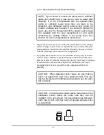
Page 21: ...refully remove the two Allen nuts at the front of the pump head CAUTION Use care when removing the pump head Twisting the pump head can cause the piston to break 9 Carefully separate the pump head fro...

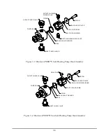
Page 22: ...ELF FLUSH HOUSING SELF FLUSH SEAL SEAL BACKUP PLATE PISTON Figure 5 1 Stainless Steel Self Flushing Pump Head Assembly PUMP HEAD OUTLET CHECK VALVE INLET CHECK VALVE SEAL SEAL BACKUP WASHER O RING SEL...

Page 23: ...VALVE O RING OUTLET CHECK VALVE PUMP HEAD INLET CHECK VALVE Figure 5 3 Bioclean PEEK Self Flushing Pump Head Assembly O RING SEAL BACKUP WASHER SEAL SELF FLUSH HOUSING SEAL BACKUP PLATE PISTON HOLE P...

Page 24: ...nd avoid scratching the sealing surfaces Repeat for the self flush housing Be sure no fibers from the cleaning swab remain in the components 2 The pump head check valves and self flush housing may be...

Page 25: ...rn past finger tight NOTE The inlet check valve has a larger opening 1 4 28 flat bottom seat for the 1 8 inlet tubing the outlet check valve has a smaller opening 10 32 cone seat for the 1 16 outlet t...

Page 26: ...Valves 5 2 3 Replacing Piston Seals Lower than normal pressure pressure variations and leaks in the pumping system can all indicate possible problems with the piston seal Depending on the fluid or mo...

Page 27: ...couring pad included in the seal replacement kit to clean the piston Gently squeeze the piston within a folded section of the pad and rub the pad along the length of the piston Rotate the piston frequ...

Page 28: ...tation is not important in these cases 4 Attach the pump head as described in Section 5 2 5 Use caution so as not to damage the sapphire piston 5 Condition the new seal as described in Section 5 3 5 2...

Page 29: ...iggling the pump head to center it CAUTION Use care when replacing the pump head Twisting the pump head can cause the piston to break 4 Re attach the inlet and outlet lines Reconnect the self flush li...

Page 30: ...the entire time they are not installed in the pump head The assemblies may fall apart parts may be lost and they may not operate properly when re assembled 5 5 Pulse Damper Replacement 5 5 1 Removing...

Page 31: ...or P3 5 Replace the cover on the pump 5 6 Cleaning the Pump 1 Disconnect the column inlet tube from the column 2 Direct the column inlet tube the tube from the injector outlet to a waste beaker 3 Set...

Page 32: ...body of the piston carrier as this can retard its movement and interfere with proper pumping NOTE Keeping the interior of the pump free of dirt and dust will extend the pump s useful life 5 8 Other P...

Page 33: ...7 14 The Pump mechanism Control Boards Pulse Dampener with Pressure Transducer are accessible by removing pump drawer...

Page 34: ...d on the circuit board and is in series with the 24 VDC supply Troubleshooting the fuses is straightforward If the power cord is plugged in and the on off power entry switch is on and the display does...

Page 35: ...ppear the battery will need replaced CAUTION Be sure to disconnect power cord before removing cover to insure there is no voltage present CAUTION Circuit boards can be damaged by Electro Static Discha...

Page 36: ...ower surge 2 Internal short 1 Replace only with the appropriate fuses 1A for 100 110 Vac or 1 2A for 220 240 Vac 2 Contact service technician if problem persists Blue dye in mobile phase Pulse damper...

Page 37: ...1 Binary Drive Assembly 880971 Front Panel Assembly 880806 Fuse 2 Amp 5x20 mm 10 pack Specific to Left Hand Pump Drawer with Pressure 880613 Repl Pulse Damper with Pressure Transducer Stainless 880144...

Page 38: ...Front Panel Assembly 880806 Fuse 2 Amp 5x20 mm 10 pack Specific to Left Hand Pump Drawer with Pressure 880614 Repl Pulse Damper with Pressure Transducer PEEK 880144 SMT Board Set with Pressure 880972...

Page 39: ...nd 2 DSR Handshaking input to pump 3 RXD Serial data input to pump 4 TXD Serial data output from pump 5 DTR Handshaking output from pump Special wiring considerations Use the following chart for inter...

Page 40: ...er of an incomplete command was sent The command packets are as follows Command Response Comments RU OK Sets the pump to the RUN state ST OK Sets the pump to the STOP state FLxxx OK Sets the flow rate...

Page 41: ...immediately RF OK x y z Reads the fault status where x Motor stall fault 0 no 1 yes y Upper pressure limit fault 0 no 1 yes z Lower pressure limit fault 0 no 1 yes KD OK Disables the keypad Default s...

Page 42: ...Terminal Board Connectors A 4 pin terminal board connector and a 10 pin terminal board connector are provided on the back panel Any device capable of providing the proper run stop logic level flowrate...

Page 43: ...connect the column from pumping system and operate the pump with the mobile phase and flow rate to be used in the analysis Observe the resulting pressure displayed on the pump readout The column will...

Page 44: ...nternally connected to the pump s chassis ground and should be connected to the controlling device s ground or zero volt terminal when the controlling device has an open collector output an open drain...

Page 45: ...press in and hold the DOWN ARROW button while turning the power switch ON b Release the DOWN ARROW button and either a U closest approximation to V for voltage or an F for frequency will be displayed...

Page 46: ...APPENDIX B EZ GRIP FITTING GUIDE A 8...

Page 47: ...horized by SSI to the extent that such repair or alteration caused the failure or to Product that has been subjected to misuse negligence accident excessive wear or other causes not arising out of a d...

Page 48: ...A 10 IMPLIED INCLUDING WITHOUT LIMITATION ANY WARRANTY OF MERCHANTABILITY OR FITNESS FOR A PARTICULAR PURPOSE...

Reviews: