SMART CELLAR INVERTER COOLING UNIT
Installation of the Condensate Pipe
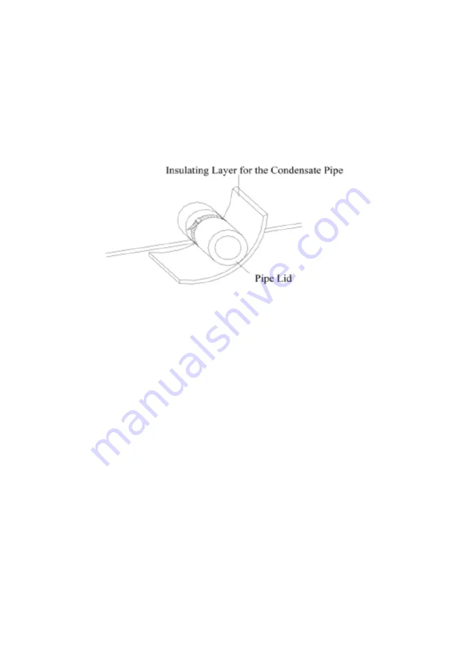
1. The condensate pipe should be installed at an angle of 5 - 10° to facilitate the drainage of
condensate water from the unit. The condensate pipe should be insulated to minimise condensation
(See Figure 13).
Figure 13: Thermal Insulation of the Condensate Pipe
2. The unit is fitted with a condensate outlet on both the left and right sides of the unit, to aid in
installation. Only one drain should be used and the other should be blanked off, sealed and
covered with insulation to avoid water leakage.
3. The right outlet is blanked off by default.
CAUTION
• Condensate pipe joins should be checked and sealed to prevent water leakage.
Condensate Drain Pipe Design and Installation
1.
!"#$%&'(#)#*$+,$)"#$%*'&-$.&.#$/"+01%$2#$1'*3#*$+*$#40'1$)+$)"')$+,$)"#$*#,*&3#*'-)$.&.#$5678$
.&.#9$+0)#*$%&'(#)#*:$;<((9$='11$)"&>?-#//$@AB<((CB
2. The drain pipe should be as short as possible.
3. The drain pipe should be maintained at an angle of 1/50 ~1/100 to avoid water becoming
trapped or air pockets forming.
4. If sufficient angle cannot be provided, a lift pipe should be installed.
5. A maximum distance of 1-1.5m should be kept between the hangers to avoid the drain hose
sagging (see Figure 14).
6. Do not use excessive force when connecting the drain pipe to the unit. The end of the pipe
should be fixed as close as possible to the side of the unit.
7. The drain pipe is not supplied with the unit and should be provided by others. Slide the end of
the PVC pipe over the drain outlet and secure it with a hose clamp. Never connect the drain
pipe to the outlet by adhesive. (See Figure 15)
WWW.AIRSHEPHERD.COM.AU
9


