background image


21

For all VibChecker versions, measurement is started 
manually from the 

Measurement

 display, which is 

opened by pressing the 

MEASURE

 key from anywhere 

in the menu structure. 

If the instrument is on and the backlight is off, nothing 
happens at first keypress, except that the backlight comes 
on. Next keypress will perform the intended action. 

Before measurement, make sure that  ISO standard, sen-
sor settings, units etc. are set up. 

To perform a vibration measurement:

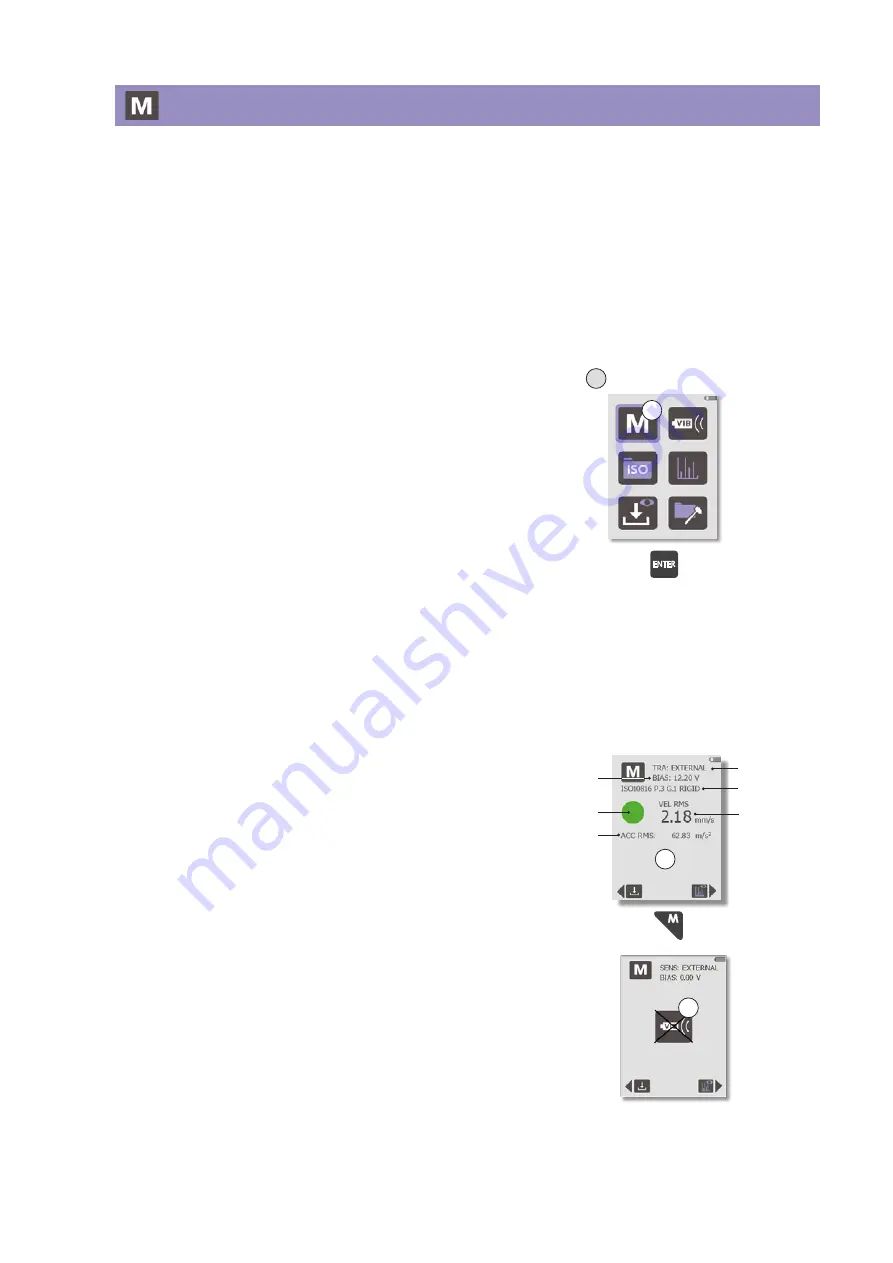
1.  In the 

Main

 display (A), select the 

Measure

 icon (B) 

and press 

ENTER

. The 

Measurement

 display opens, 

showing the most recent reading. 

2.  For a new measurement, point the VibChecker 

straight at the measuring point and press the probe 
tip until the rubber sleeve is in contact with the 
surface (or connect the external sensor). 

3.  Hold the instrument steady and press the 

MEASURE


key to start measurement. A single blue pixel briefly 
appears at the bottom of the display, indicating that 
a measurement cycle  - beginning with an automatic 
bias check - is in progress. The display backlight is 
then turned off until the measurement is completed.


When using an external sensor, the actual measuring 
starts when the defined settling time has elapsed. 
As long as the 

Measurement

 display is still selected 

and the backlight is on, no new settling time is 
needed to make further measurements, unless you 
switch to using the built-in measuring probe. 

4.  When the display lights up again, it shows the 

measurement result according to the settings made 
in the instrument (C). The result is shown in large 
numbers, with alternative values (RMS, peak, and 
peak-to-peak, depending on the selected vibration 
quantity) shown in small numbers below. Depend-
ing on vibration severity (and provided that an ISO 
standard was selected), the display shows a green, 
yellow or red condition indicator. 


When an external sensor is used, the instrument dis-
plays the bias voltage level for the current reading in 
the upper part of the display. If the reading was made 
with a poor sensor line, the instrument will display 
Bias error (D). For further information about bias 
problems, please see the “Bias voltage” section.

To return to the 

Main

 display, press the 

BACK

 key. 

For information on how to store and analyze meas-
urement results, see sections ‘Storing measurement 
results
’ and ‘Spectrum analysis’, respectively.

Measurement 

Condition 

status

ISO settings

Alternative 

value(s)

Measure- 

ment value

Bias voltage

Sensor type

C

A Main display

B

D

Summary of Contents for VibChecker

Page 1: ...User Guide v i b c h e c k e r c o m s p m i n s t r u m e n t c o m vibration monitoring to go make MAINTENANCE A PROFITABLE PART OF YOUR PRODUCTION ...

Page 2: ...ment AB Box 504 SE 645 25 Strängnäs Sweden Technical data are subject to change withput notice Tel 46 152 225 00 info spminstrument se www spminstrument com ISO 9001 certified Copyright SPM 2019 04 72220 B Rev 0 ...

Page 3: ...easuring points 20 Measurement 21 Recording readings for follow up 22 Storing measurement results 23 Spectrum analysis 24 Spectrum display 24 Zoom 24 RPM manual input 25 Adding markers for harmonics 25 Time signal analysis 26 Time signal display 26 Zoom 26 ISO 2372 27 Evaluation of machine condition 27 Definition of machine classes according to ISO 2372 28 ISO 10816 29 ISO 10816 Part 2 29 ISO 1081...

Page 4: ...2 ...

Page 5: ...ly be used for their respective intended purpose as defined in this User Guide The instrument must not be used in environments outside of the tem perature range specified under Technical specifications in this User Guide as the battery may be damaged and may cause harm or danger When measuring ensure that no cables etc can be caught in rotating parts which can cause injury For safety reasons the m...

Page 6: ...ion Excessive vibration basically has three potential causes something is loose misaligned or out of balance These three causes cover virtually all possible mechanical faults Moreover the assessment of machine vibration has been much simplified by international standards which define the acceptable vibration level for a given type of machine and recommend monitoring methods suitable for industrial...

Page 7: ...ost is often as useful as a detailed analysis using expensive equipment and elaborate techniques VibChecker is battery powered and designed for use in harsh industrial environments The graphical display C shows the condition readings and if ISO 10816 or ISO 2872 is activated provides evalu ated machine condition in green yellow red The instrument has a built in probe sensor A The external sensors ...

Page 8: ...gs Spectrum settings General settings Vibration measurement View stored readings ISO setup Navigation keys Go back one step from anywhere in the menu structure Measure vibration levels from anywhere in the menu structure Confirm setting Save reading ...

Page 9: ...7 General settings Vibration quantity settings Factory reset Date and time Units of measurement About Display contrast and screensaver settings ...

Page 10: ...alysis Save result to memory Condition status ISO settings Alternative value s Measurement value View spectrum and time signal Measurement Zoom in Zoom out Move right Move left Spectrum Step right Step left RPM manual input Markers 1X 5X ...

Page 11: ...icates that a charging cable is inserted When the battery charge icon is green the battery is charging When it turns gray the battery is fully charged Should the battery charge icon be full but in red color something is wrong with the charging system or circuitry and the instrument needs to be sent to SPM Instrument for service Extending battery life Avoid deep cycling of the battery Each cycle we...

Page 12: ...ically and successively goes into energy saving mode first by dimming the display backlight accord ing to the user defined screensaver timeout for more information see chapter Display contrast and screensaver timeout in this user guide Next after another twenty seconds the backlight turns off entirely with the instrument still running At this stage reactivate the backlight by pressing any key Fina...

Page 13: ...ment and units Available settings include the metric or imperial sys tem frequency in Hz Herz cycles per second or CPM cycles per minute similar to RPM and acceleration in g or m s2 To make your settings 1 Go to the Main display A 2 Use the arrow keys to navigate to the General Set tings icon B then press ENTER 3 In the General settings display select the Units icon C and press ENTER 4 In the Unit...

Page 14: ...save your settings and re turn to the General settings menu To return to the Main display press the BACK key Date time It is essential that the instrument has the correct date and time to avoid confusion when saving measuring results to memory To set date and time 1 Go to the Main display A 2 Use the arrow keys to navigate to the General Set tings icon B then press ENTER 3 In the General settings ...

Page 15: ...display shown next further settings are required with one exception For ISO 10816 Use the UP DOWN arrow keys to select PART 2 3 or 4 When PART 2 is selected D step to RPM with the RIGHT arrow key then use the UP DOWN keys to select 1500 or 1800 or 3000 or 3600 When PART 3 is selected E step to GROUP with the RIGHT arrow key and use the UP DOWN keys to select GROUP 1 4 Then move on to the SUPPORT s...

Page 16: ...n the first of two AVD displays D use the UP DOWN arrow keys to highlight the appropriate vibration quan tity and press ENTER to mark it The second display opens E NOTE If an ISO standard has been activated in the ISO setup display only VEL can be selected here for more information see section ISO standard setup 5 Using the UP DOWN arrow keys highlight the check box of the metrics to show in the M...

Page 17: ... will perform four measurements and then display an average of the measurement results To set a number of spectrum lines 1 Go to the Main display A 2 Use the arrow keys to navigate to the Spectrum set tings icon B then press ENTER 3 In the Spectrum settings display use the UP DOWN arrow keys to highlight the checkbox for your preferred number of lines and press ENTER to mark it 4 If averaging shou...

Page 18: ...the BACK key Pressing the ENTER key will reset the instrument back to the default settings listed on page 11 Serial number and software version To find out the software version and instrument serial number 1 Go to the Main display A 2 Use the arrow keys to navigate to the General Set tings menu B then press ENTER 3 In the General settings display select the Informa tion icon C and press ENTER 4 Th...

Page 19: ...her manufacturers have actual sensitivities and settling times written on their calibration cards When several sensors are in use they should be marked to assure that the readings are calibrated Sensors with magnets option The vibration sensors with magnets TRM100 and TRM120 options can be used for attachment to fer rous metal parts to reach measuring points in narrow spaces and has the same const...

Page 20: ... instrument Part of your signal will be lost in a poor sensor line so your measuring results will be incorrect If a measurement is made with a poor sensor line the instrument will display Bias error If there is an open circuit broken cable or no sensor connected the bias value is 16 V If the bias value is 8 V the connectors cable and sensor should be checked for short circuit ...

Page 21: ...one direction peak or as the total movement in both directions peak to peak Displacement is expressed in micrometers VibChecker always measures an acceleration signal which is integrated to obtain the velocity and double integrated to derive displacement Both acceleration and speed are constantly changing One can measure a peak value of either but a mean value often gives a better indication of th...

Page 22: ... 110 C 230 F Spare sleeves have part number 18128 Avoid small cavities and fillets Measuring points Vibration severity is primarily a measure for general machine condition Vibration at the measuring point should be representative for the overall vibration of the machine Typical measuring points are on the bearing housings By measuring in three directions one can get an indication of the causes for...

Page 23: ...or the actual measuring starts when the defined settling time has elapsed As long as the Measurement display is still selected and the backlight is on no new settling time is needed to make further measurements unless you switch to using the built in measuring probe 4 When the display lights up again it shows the measurement result according to the settings made in the instrument C The result is s...

Page 24: ...h should adequately cover most industrial machines Experience will soon show which of the measuring points and directions provide the most useful information for diagnosing a specific problem on any particular piece of machinery A graph is the best way to show clearly all significant changes of the vibration level To keep the form simple draw only the graph for the most significant direction norma...

Page 25: ...ng spectrum can be transferred from VibChecker to a Microsoft Excel file using a downloadable SPM program http downloads spminstru ment com The data in the Excel file can be imported into a CMMS or other software for follow up For further instructions please see information in the delivery package As an alternative the final pages of this User Guide contains a follow up form which can be copied an...

Page 26: ... see the Spectrum resolution settings section compressed to screen resolution for full view The spectrum is zoom able see below Zoom The zoom functionality works as follows To zoom in use the UP arrow key Please be obser vant that the Y scale will change adapting to the zoomed in view To zoom out use the DOWN arrow key To move the zoom window along the X axis use the LEFT RIGHT arrow keys The uppe...

Page 27: ...ans that the line or group of lines is repeated two three or more times further up in the spectrum The spacing is a multiple of the RPM frequency To display harmonics up to five markers 1X 2X 3X can be input and shown in the spectrum Before using this function the rotational speed must be input first see above A 1X marker then appears in the spectrum if the marker is not visible zoom out with the ...

Page 28: ...nal in milliseconds is determined by the resolution selected under Spectrum settings for more information see the Spectrum resolution settings section 200 lines 200 ms 400 lines 400 ms 800 lines 800 ms The time signal is zoomable see below Zoom The zoom functionality works as follows To zoom in use the UP arrow key Please be obser vant that the Y scale will change adapting to the zoomed in view To...

Page 29: ...ut special supports Class III Large size machines on rigid supports Class IV Turbomachines and large machines on flexible supports For example most smaller process pumps in a chemical plant would be Class 2 A 100 kW fan on a concrete foundation would be Class 3 However the same fan fastened to the less rigid metal deck of a ship could be considered as Class 4 Class 1 refers to independent parts of...

Page 30: ...sized machines typically electrical motors with 15 to 75 kW output without special founda tions rigidly mounted engines or machines up to 300 kW on special foundations Class III Large prime movers and other large machines with rotating masses on rigid and heavy foundations which are relatively stiff in the direction of vibration measurement Class IV Large prime movers and other large machines with...

Page 31: ...This machine class has no sub group Instead the choice of limit value table depends on machine speed either 1500 1800 r min or 3000 3600 r min Selecting the appropriate speed range results in a measurement setup with the ISO recommended fre quency range 10 to 500 Hz the recommended measurement quantity vibration velocity VEL and the limit values or zone boundaries A measurement result below the zo...

Page 32: ...80 4 5 0 18 Flexible Green Yellow 71 2 80 4 5 0 18 Yellow Red 113 4 45 7 1 0 28 Group 2 Evaluation zone boundaries for machines of Group 2 Medium size machines with rated power above 15 kW up to and including 300 kW electrical machines with shaft height 160 mm H 315 mm Support class Condition DISP VEL Zone boundary RMS displacement RMS velocity µm mils mm s in s Rigid Green Yellow 36 1 42 4 5 0 18...

Page 33: ...low Red 14 7 0 58 Evaluation zone boundaries based on bearing housing pedestal vibration velocity valid for shaft rota tional speed 3000 RPM to 20 000 RPM Note These values which are the upper limits of the zones should apply to radial vibration measure ments on all bearing housings or pedestals and to axial vibration measurements on housings containing an axial thrust bearing under steady state o...

Page 34: ... LED backlight Keypad sealed snap action Material casing copolyester TPE Power supply 3 63 V Lithium Ion USB rechargeable Battery life 25 hours of typical use Built in sensor accelerometer type MEMS Input connector mini coax for external sensor External sensors vibration transducer TRM100 TRM120 or IEPE ICP type transducers with voltage output Output connector mini B USB Operating temperature 10 C...

Page 35: ...s as a first priority the prevention of waste electrical and electronic equipment WEEE and in addition the reuse recycling and other forms of recovery of such wastes so as to reduce the disposal of waste This product must be disposed of as electronic waste and is marked with a crossed out wheeled bin symbol in order to prevent it being discarded with household waste Once the life cycle of the prod...

Page 36: ...7 1 1 1 8 0 5 0 7 1 15 0 3 0 5 0 7 CLASS CLASS 1 DATE 45 71 110 28 45 71 18 28 45 11 18 28 7 1 11 18 4 5 7 1 11 2 8 4 5 7 1 1 8 2 8 4 5 1 1 1 8 2 8 11 18 28 7 1 11 18 4 5 7 1 11 2 8 4 5 7 1 1 8 2 8 4 5 1 1 1 8 2 8 0 7 1 1 1 8 0 5 0 7 1 15 0 3 0 5 0 7 45 71 110 28 45 71 18 28 45 11 18 28 7 1 11 18 4 5 7 1 11 2 8 4 5 7 1 1 8 2 8 4 5 1 1 1 8 2 8 11 18 28 7 1 11 18 4 5 7 1 11 2 8 4 5 7 1 1 8 2 8 4 5 1...

Page 37: ... 0 18 0 28 0 07 0 11 0 18 0 04 0 07 0 11 0 03 0 04 0 07 0 02 0 03 0 04 0 01 0 02 0 03 0 43 0 71 1 10 0 28 0 43 0 71 0 18 0 28 0 43 0 11 0 18 0 28 0 07 0 11 0 18 0 04 0 07 0 11 0 03 0 04 0 07 0 02 0 03 0 04 0 01 0 02 0 03 0 43 0 71 1 10 0 28 0 43 0 71 0 18 0 28 0 43 0 11 0 18 0 28 0 07 0 11 0 18 0 04 0 07 0 11 0 03 0 04 0 07 0 02 0 03 0 04 0 01 0 02 0 03 1 77 2 80 4 30 1 10 1 77 2 80 0 71 1 10 1 77...

Reviews: