Spirax Sarco RIM10 Series Installation And Maintenance Instructions Manual Download Page 80

IM-P198-02 

 MI Issue 5

80

5.

   The  Data  Log  page  shows  a  list  of  selected  flow  parameters  that  are  saved  to  flash 

memory at selected intervals. The data log will wrap after 'x' lines. 

To view faults and history, return to the service console by clicking the Service button.

At the Service Console, click either the View History data or View fault/event log buttons.

4. 

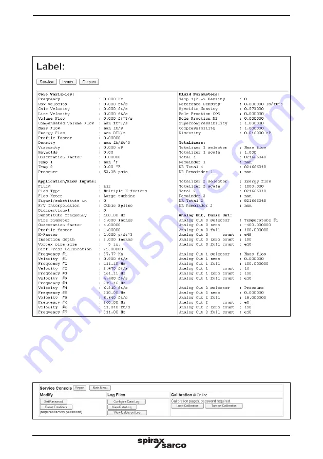
  The report page is a condensed text display of all internal settings. To view an output 

or input report, click on the Report button in the Operations line. 

Fig. 91

Fig. 92

Summary of Contents for RIM10 Series

Page 1: ...ons 1 Safety information 2 General product information and Guide to installation 3 Mechanical installation 4 Electrical installation 5 Configurating your flowmeter 6 RIM10 Series web interface 7 MODBU...

Page 2: ...IM P198 02 MI Issue 5 2...

Page 3: ...N 61326 1997 Electrical equipment for measurement control and laboratory use EMC requirements Immunity to industrial locations annex A Table A1 Emissions to domestic locations Table 4 For hazardous lo...

Page 4: ...e manner specified by this IMI then the protection provided may be impaired Special conditions for safe use of this product 1 The RIM10 enclosure contains aluminum and is considered to present a poten...

Page 5: ...ill any proposed action e g closing isolation valves electrical isolation put any other part of the system or any personnel at risk Dangers might include isolation of vents or protective devices or th...

Page 6: ...of the product may be very hot If used at the maximum permitted operating conditions the surface temperature of some products may reach temperatures of 400 C 750 F Many products are not self draining...

Page 7: ...rated and inspected to ensure proper operation Receipt of shipment Each carton should be inspected at the time of delivery for possible external damage Any visible damage should be recorded immediatel...

Page 8: ...insertion flowmeters These flowmeters should always be self draining Overhead clearance A minimum of 300 mm 12 of overhead clearance is recommended for ease of installation Easy accessibility The ins...

Page 9: ...nents that may add disturbances to the flow If such conditions exist and or sufficient straight pipe is unavailable a flow conditioner may be used to improve measurement conditions The minimum straigh...

Page 10: ...g runs See Figure 3 It is important for the pipe to be full for accurate measurements Follow the guidelines below for the recommended location for installation Fig 3 All media Liquid Liquid Liquid Gas...

Page 11: ...ch service has been shutdown A hot tap installation involves drilling a hole into a pressurised line without line shutdown and disruption of the process The RIM10 600 and RIM10 900 rotor insertion flo...

Page 12: ...or line depressurisation The RIM10 600 is shipped with an isolation valve and a pipe nipple attached to the flowmeter See Figure 6 For a hot tap installation the isolation valve and pipe nipple need...

Page 13: ...Turn the retractor handle RIM10 600 series or wheel RIM10 900 series to insert the tap check tool into the pipe and then retract the tap check tool completely Close the isolation valve Slowly open th...

Page 14: ...e bleed valve is closed Open the isolation valve Turn the retractor handle RIM10 600 series or wheel RIM10 900 series to insert the tap check tool into the pipe and then retract the tap check tool com...

Page 15: ...alve and thread o let E for the RIM10 900 Distance from the top of the isolation valve to the outside pipe wall Wt Thickness of the pipe wall The disk cut out or coupon from the tapping procedure can...

Page 16: ...calculated scale reading on the depth scale lines up with the arrow on the retractor bar assembly If the rotor is a 38 mm 1 5 size RIM10 600 with ASME ANSI Class 150 flanged connection line up the bo...

Page 17: ...or bar assembly so the flow direction arrow on the cursor is in line with the pipe and pointed downstream Lock the stem in position by tightening the orientation set screw See Figures 11 and 12 Cautio...

Page 18: ...he flowmeter to the flange Verify that the bleed valve is closed Use the orientation levers to manually lower the tap check tool into the pipe and then retract the tap check tool completely Remove the...

Page 19: ...ely Remove the flowmeter from the thread o let and inspect the tap check took for damage If any has occurred check the installation for possible clearance problems Step 4 Remove the tap check tool and...

Page 20: ...er can also be obtained from a piping handbook Example An RIM10 700 with a G6 rotor is to be installed on a 300 mm 12 Schedule 40 pipe The following measurements have been obtained C 362 mm 14 25 I 30...

Page 21: ...tion by tightening the Swagelok fitting Verify insertion depth prior to final tightening of the fitting When the fitting has been tightened the stem position becomes permanent and cannot be changed 3...

Page 22: ...eving satisfactory performance and reliability Spirax Sarco recommend the following 1 Use shielded wire for all inputs and outputs For example use Belden 9451P for 4 20 mA current loops especially in...

Page 23: ...ent earth ground at the control panel Plastic pipelines require the transmitter condulet to be connected to an earth ground To do this connect the condulet to the earth ground by attaching a cable or...

Page 24: ...C1_SENSE_IN C1_SHIELD_DRV C2_SHIELD_DRV C2_SENSE_IN C2_SENSE_IN RTD_COMP RTD RTD CONN3 Remote head Conn1 1 Conn3 9 Conn2 1 5 1 12 24 13 J3 J3 to user wiring 4_20_OUT1 _C 4_20_OUT1 _C 4_20_OUT2 _C 4_20...

Page 25: ...c power as shown in Figure 20 using 0 82 mm2 0 33 mm2 18 22 AWG gauge wire The dc supply can be anywhere from 12 32 V but 24 V is recommended On installation the RIM10 shall be provided with supply tr...

Page 26: ...current loop input Three channels are available 4 20 mA inputs cannot be used to power the loop interface For the inputs the transmitter output is tied to the positive terminal and the negative termin...

Page 27: ...ons make use of flat thin jump strips that allow the 2 additional wires into those terminals Each transmitter is connected between the 24 V supply and In Each receiver is connected between the Out and...

Page 28: ...g voltage The maximum current and voltage in hazardous environments is 50 mA and 24 V An alternate view of the relay contacts is shown below Fig 25 Fig 26 RIM10 terminal 10 Relay 1 Normally closed con...

Page 29: ...wires would go on to the next node In this case the first paired cable would be connected to pins 1 and 4 and the second paired cable would be connected to pins 2 and 5 Placing a jumper between pins 1...

Page 30: ...wed and wiring runs measured prior to installation Failure to observe maximum wiring lengths can prevent the flowmeter from operating and may void the warranty In the remote mount situation the shield...

Page 31: ...es 1 Use twisted wire for the wire pair C1_SENSE_IN P3 Terminal 1 and C1_SENSE_IN P3 Terminal 2 2 Use twisted wire for the wire pair C2_SENSE_IN P3 Terminal 5 and C2_SENSE_IN P3 Terminal 6 3 Use twist...

Page 32: ...will not actuate the key it must be turned on then off to be sensed as a valid key press by the flowmeter Navigating the menus involves using the up and down arrow keys to select high light an option...

Page 33: ...move between screens in this mode The up and down arrows control the LCD contrast in Run mode To make the screen darker press and release the up arrow key To make the screen lighter press and release...

Page 34: ...ond type contains a display window and a bottom line for viewing or editing operations See Figure 34 The bottom line has 3 selectable fields a left arrow text and a right arrow Selecting the left arro...

Page 35: ...en example Figure 35 Fig 35 Data edit screen example Press right key Press enter key Press right arrow key Press enter key Pressing the enter key when the left arrow symbol is selected returns to the...

Page 36: ...The user can return to Run mode by selecting the Return to Display option The following pages show how to navigate the sub menus Duplicate paths through the menus are not shown and the scrolling list...

Page 37: ...the maximum measured value and line 3 shows the minimum measured value Main Menu Return to Display Reset Totalisers Reset Min Max Display Set up Set up Wizard Network Set up Set Time Date Faults Servi...

Page 38: ...ax Display Set up Set up Wizard Network Set up Set Time Date Faults Service Enter right arrow Set up Display Screens On Off Display Unit LCD set up Enter right arrow The asterisk indicates this screen...

Page 39: ...Menu Return to Display Reset Totalisers Reset Min Max Display Set up Set up Wizard Network Set up Set Time Date Faults Service Enter right arrow Set up Display Screens On Off Display Unit LCD Set up E...

Page 40: ...t up Display Screens On Off Display Unit LCD Set up Enter right arrow Choose units Velocity Mass Flow Energy Flow Volume Flow Temperature Pressure Density Note Use the up down keys to select the desir...

Page 41: ...isplay Reset Totalisers Reset Min Max Display Set up Set up Wizard Network Set up Set Time Date Faults Service Enter right arrow Enter Meter label Meter 5 SELECT Enter right arrow Product code 123 456...

Page 42: ...t Linear Cubic Spline From page 41 Edit frequency velocity pairs No changes Edit existing Enter right arrow Forward or reverse FWD cal data Rev cal data Enter right arrow Fwd frequency 1 37 67 Hz SELE...

Page 43: ...ht arrow Choose down stream temp sensor None Internal RTD 4 20 mA T 1 4 20 mA T 2 Substitute Enter right arrow Select temp sensor input for density measurement Temp 1 input Temp 2 input Enter right ar...

Page 44: ...mp flow Mass flow Energy flow Enter right arrow From page 43 Total 1 units Ft 3 In 3 bbl cc l m 3 qt Enter right arrow 1 Scale factor 10 SELECT Enter right arrow Totaliser 2 assignment None Volume flo...

Page 45: ...ts No changes Analog out 1 Analog out 2 Analog 3 Enter right arrow Select parameter None Temperature Temperature _2 Diff temp Pressure Density Velocity Volume flow Comp flow Mass flow Energy flow Ente...

Page 46: ...ge 47 Select limit low hi window Enter right arrow Select hystersis 1 EDIT Enter right arrow Set high limit 100 F EDIT Enter right arrow Fig 47 Relay 1 None Temp 1 alarm Temp 2 alarm Diff temp alarm P...

Page 47: ...m Diff temp alarm Pressure alarm Density alarm Velocity alarm Volume flow alarm Comp flow alarm Mass flow alarm Energy flow alarm Enter right arrow None To page 48 Select limit low hi window Enter rig...

Page 48: ...lse transit Relays Fwd Rev Enter right arrow Set Maximum freq 500 Hz 1 kHz 2 kHz 3 kHz 5 kHz 10 kHz Enter right arrow Enter min flow rate 0 EDIT Enter right arrow Enter max flow rate 450 EDIT Set Puls...

Page 49: ...Display Set up Set up Wizard Network Set up Set Time Date Faults Service Enter right arrow Set up network ModBus Ethernet Enter right arrow ModBus Connections None RTU TCP Enter right arrow Enter slav...

Page 50: ...et Totalisers Reset Min Max Display Set up Set up Wizard Network Set up Set Time Date Faults Service Enter right arrow Set up network ModBus Ethernet Enter right arrow ModBus Connections None RTU TCP...

Page 51: ...etwork Set up Set Time Date Faults Service Enter right arrow Set up Network ModBus Ethernet Enter right arrow Enter Domain name Emcoflow com SELECT Change settings no yes Fig 53 Enter Hostname Emco En...

Page 52: ...x Display Set up Set up Wizard Network Set up Set Time Date Faults Service Fig 54 Enter right arrow Edit local date month December 19 2011 EDIT Enter right arrow Edit local hours minute 13 04 30 EDIT...

Page 53: ...will not clear until the cause of the fault is corrected For a complete list of fault error codes see pages 82 and 83 Main Menu Return to Display Reset Totalisers Reset Min Max Display Set up Set up W...

Page 54: ...Select channel Cal ch 1 output Cal ch 2 output Cal ch 3 output Cal ch 1 input Cal ch 2 intput Cal ch 3 input Enter Terminals 7 to 13 8 to ammeter 1 to ammeter Enter Output now set to approx 3 47 mA E...

Page 55: ...in Figure 57 illustrates how to change the password Contact the factory for the service default password Main Menu Return to Display Reset Totalisers Reset Min Max Display Set up Set up Wizard Networ...

Page 56: ...ts Factory Enter right arrow Output tests Relay 1 Test Relay 2 Test Pulse Output Test Main Menu Return to Display Reset Totalisers Reset Min Max Display Set up Set up Wizard Network Set up Set Time Da...

Page 57: ...t Show all values Displays all inputs and outputs Main Menu Returns to main menu Online Offline Display current network connection Faults Current faults Values Displays chosen values The green on line...

Page 58: ...ection 6 2 Display set up Section 6 3 Network set up Section 6 4 Time set up Section 6 5 Reset totalizers Section 6 6 Reset min max Section 6 7 Service Section 6 8 Return to display mode There are two...

Page 59: ...a saved configuration file To select a configuration file to load select one of the following from the drop down menu Current User 1 Configuration file User 2 Configuration file Last back up of the pr...

Page 60: ...If any of this data is incorrect click on the Edit button and you will be guided through the various flowmeter data screens Meter Label Tag Number Pipe Inside Diameter Settings Turbine Size Settings s...

Page 61: ...be measured with accompanying values are edited on this screen Select a measurement type Steam volume Steam controlled Steam saturated Steam uncontrolled superheated Steam condensate Gas volume Gas m...

Page 62: ...Choose the type of temperature measurement Fahrenheit Celsius Kelvin For substitute values enter the temperature and choose the temperature measurement Fahrenheit Celsius Rankine Kelvin For pressure...

Page 63: ...gy flow Btu Kj Cal Kcal Mcal Ton Kw Mw gw Edit the totalizer scale factor for the measurement selected Repeat process for Totalizer 2 For Analog Outputs 1 3 Select an analog output parameter None Temp...

Page 64: ...se output function None Scaled frequency Sensor frequency 50 duty cycle Pulse negative Pulse positive Transit For Scaled frequency select one of the following Out min Out max Out max freq 1 khz For Se...

Page 65: ...creen 6 3 Display set up Click the Display Set up button to go to the Display Configuration Menu where you can choose the parameters you wish to see on the Operating Display screen Check the box besid...

Page 66: ...gs for the RIM10 flowmeter Select either Ethernet Section 6 4 1 or Modbus Network Section 6 4 2 6 4 1 Ethernet Network set up wizard The current Ethernet settings are displayed Select Next to change t...

Page 67: ...x To select a new domain type the new domain name in the box displayed Click on Next to move to Step 2 Step 2 Current IP address Step 3 Routing The new settings are shown This saves the changes to all...

Page 68: ...After selecting the Modbus Network the following screen appears Enter the following New Unit number 1 247 New Modbus protocol The default Modbus TCP port number is 502 Select Next to move on to the ne...

Page 69: ...turned to the Main Menu Or you can click on the Main Menu button to cancel changes and return to the Main Menu screen Step 2 Communication parameters Enter the following New baud rate New number of bi...

Page 70: ...t up 6 6 Reset Totalizers 6 7 Reset Min Max 6 8 Service For user of the service options in the RIM10 web interface refer to Section 8 Diagnostics and Calibration and Section 9 Troubleshooting and Main...

Page 71: ...r and external current source set the input current to 4 00 mA Step 3 Enter the current into the Enter Input Current 1 box and click the save_input 1 button Step 4 Using an ammeter and external curren...

Page 72: ...RIM10 calibration The following will assist the user in entering frequency velocity data for a calibrated RIM10 Note this data should not be changed unless the user is replacing a damaged RIM10 and ha...

Page 73: ...og file 6 8 4 Service view data log The following will assist the user to see the contents of the data log Note the parameters are all comma separated to allow easy transfer to a spreadsheet When a Cl...

Page 74: ...s The LCD or Web page interface documentation provides details on flowmeter operation Note Always power cycle the flowmeter after making any changes to the Modbus configuration 2 Physical Wiring TCP I...

Page 75: ...s to read Hi byte 00 Bytes to read Lo byte 02 CRC Hi byte 66 CRC Lo byte 0C Response from RIM10 Field name Hex value Slave address 01 Function 03 Byte Count 04 Data Hi 40984 E9 Data Lo 40984 79 Data H...

Page 76: ...ble Totalizer 2 remainder count 11 Non resetable Totalizer 2 20629 long 4 Non resettable totalizer 2 12 Pipe diameter 40002 float 4 Pipe diameter inches 13 Temperature input 1 40984 float 4 Temperatur...

Page 77: ...41016 Float 4 4 20 mA output current channel 3 mA 38 Enthalpy 1 41022 Float 4 Water or Steam enthalpy temp input 1 Btu lb 39 Enthalpy 2 41024 Float 4 Water or Steam enthalpy temp input 2 Btu lb 40 Mi...

Page 78: ...IM P198 02 MI Issue 5 78 Appendix B Web page screen shots Fig 86 Fig 88 Fig 87...

Page 79: ...Service button to go to the Service Console page If a password has been set it will need to be entered here 6 digit number 2 Click the Inputs or Outputs buttons on the right side of the screen to go t...

Page 80: ...after x lines To view faults and history return to the service console by clicking the Service button At the Service Console click either the View History data or View fault event log buttons 4 The r...

Page 81: ...faults or significant changes in the flowmeter settings The state shows fault event activity A means a fault has been added to the list C means an existing fault is cleared Some faults are cleared au...

Page 82: ...ally rather than all at once Error Code Description 00 Substitute values in use 01 Relay 1 Alarm 02 Relay 2 Alarm 03 Meter powered down 04 Pulse out queue full pulses lost 05 4 20 Analog output 1 out...

Page 83: ...in Max compensated volume flow changed 45 Resettable Totalizer 1 cleared 46 Resettable Totalizer 2 cleared 47 Non resettable Totalizer 1 cleared 48 Non resettable Totalizer 2 cleared 49 Frequency out...

Page 84: ...n will show you how to connect the terminals 8 5 1 Output calibration 5 When the terminals have been connected as indicated select Next for the following screen 6 This screen will show Output now set...

Page 85: ...Select the bottom navigation bar to go to the next screen 25 Enter measured current message will scroll across the screen 26 Select Edit in the navigation bar to enter edit mode 27 Use the left and r...

Page 86: ...s 3 Check the rotor for bearing drag or seizure To do this check by holding the rotor assembly between the thumb and forefinger while blowing on the rotor If the bearings are worn the rotor may seize...

Page 87: ...1 Verify wiring is in accordance with the power and wiring diagrams in Section 4 Electrical installation 2 Check the power supply voltage 3 Check the voltage at the flowmeter 4 Verify the analog zero...

Page 88: ...density of fluid lbs ft 3 kg m N A No Application 3 Check the quality of the rotor signal To do so look for the turbine variation warning on the web page 9 6 Normal rotor The normal signal from the m...

Page 89: ...flow velocity can cause the rotor to overspeed The sine wave of an over ranged rotor looks as if several sine waves were superimposed on each other each wave slightly offset from the other 9 11 Chatte...

Page 90: ...IM P198 02 MI Issue 5 90...

Page 91: ...IM P198 02 MI Issue 5 91...

Page 92: ...IM P198 02 MI Issue 5 92...

Reviews: