background image

Operation 

MD-01 Driver may be operated with the use of a keyboard or a computer. 

MD-01 module has two modes (MODE). 


NORMAL – normal mode. 


MOTOR ANGLES – calibration mode. 

To change the mode, use the 

[F]

 key. 

Normal mode (NORMAL) 

In this mode the driver may be operated with the [Right], [Left], [Up] and [Down] buttons or receives 

the command from PC. The driver supports communications protocols such as SPID ROT1, SPID ROT2, SPID 
MD01, BRITE, YAESU and HyGain, which you can attribute to each communications port (COM0, COM1, USB D 
and ETH) in the settings. 

The 

[Right]

 and 

[Left] 

buttons are used to rotate the antennae in the azimuth. 

The right direction – the antennae turns in a clockwise direction, the value of the angle in the display 

increases. 

The left direction – the antennae turns in an anticlockwise direction, the value of the angle in the 

display decreases. 

The 

[Up]

 and 

[Down]

 buttons are used to rotate the antennae in the angle of elevation. 

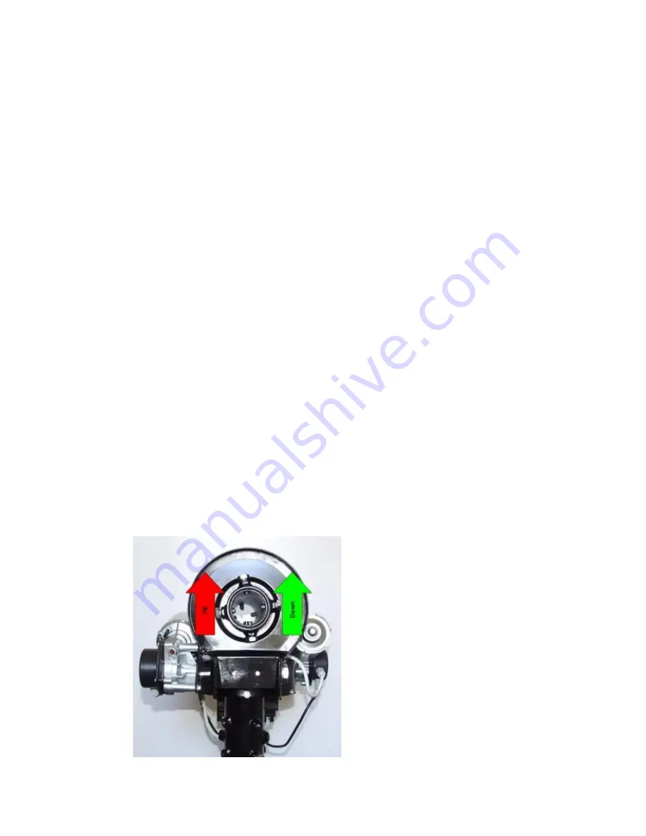
The up direction – the rotor turns right from the point of view of the front. The value of the angle in 

the display increases. 

The down direction – the rotor turns left from the point of view of the front. The value of the angle in 

the display decreases. 

The directions of antennae rotation are shown in the picture: 


Summary of Contents for MD-01

Page 1: ...SPID Elektronik Driver MD 01 MD 01 ...

Page 2: ...nt 5 Back 5 Operation 8 Normal mode NORMAL 8 Calibration mode MOTOR ANGLES 9 Driver MD 01 configuration 9 Motor configuration 9 TEMPLATE 9 Start 10 Stop 10 External control CONTROL xx 10 Protocol PROT xx 11 Set motors SET MOTOR 1 SET MOTOR 2 11 STATE 11 TYPE 11 KIND 11 INPUT 11 GEAR 11 MIN ANGLE 11 MAX ANGLE 11 MAX POWER 12 ...

Page 3: ... 12 STOP POWER STOP TIME 13 STOP AT 13 PULS TIMEOUT 13 SET COM 0 SET COM 1 13 STATE 13 BAUD 13 DATA BITS 14 STOP BITS 14 PARITY 14 SET USB COM 14 STATE 14 BAUD 14 DATA BITS 14 STOP BITS 14 PARITY 14 SET ETHERNET 14 STATE 14 ...

Page 4: ...muth rotors or double one Azimuth Elevation rotor The basic circuit provides operation with direct current motors Block diagram Parameters of the driver supply voltage of driver MD 01 15 VDC Imax 2A supply voltage of rotors 12 14 VDC Imax 40 A the maximum current of a single motor up to 20 A 2 x RS232 ports 1 x USB host port 1 x USB device visible in the system as the virtual COM port 1 x Ethernet...

Page 5: ...otor supply Elevation PINs from the motor 1 2 PINs in the driver 1 2 Every output has its own FUZE 20A 8 Switch used to update the driver software FIRMWARE To update the software we use COMO item 12 while we turn the switch OFF Normal mode of the driver is when the switch is in the PR position 9 Universal output the possibility to connect inside the module driver with relays Then the controller wi...

Page 6: ...connector Connection insite the rotor is AZ wire No1 2 EL wire 3 4 Picture of connection insite the rotor is also in the PS 01 manual Note is you did not ordered the PS 01 PSU you have to make your own connections Connection of the Sensor cable MD 01 BIG RAS HR 2 Connection of the sensor cable AZ EL Delivered is a DB9 Male connector which is used to connect to MD 01 Connection at the rotor is done...

Page 7: ...MIC328 is at the rotor DB9 Male is at the MD 01 controller back site ...

Page 8: ... in the settings The Right and Left buttons are used to rotate the antennae in the azimuth The right direction the antennae turns in a clockwise direction the value of the angle in the display increases The left direction the antennae turns in an anticlockwise direction the value of the angle in the display decreases The Up and Down buttons are used to rotate the antennae in the angle of elevation...

Page 9: ... is modular Select module using buttons Left or Right When you select module you can use button S to enter in its parameters Moving between parameters is done with buttons Left or Right Value of parameter can change with buttons Up or Down Button F is used for exiting configuration After pushing button there is question about writing current configuration If we want to confirm changes we are press...

Page 10: ... Appears only if the chosen template is different from 1 NC 2 NC If the latter is chosen template 1 AZ 2 AZ then for each motor you can choose another port for control On display of controller can show few descriptions it depends of selected motors template CONTROL A1 motor template 1 AZ 2 NC or 1 AZ 2 AZ CONTROL E2 motor template 1 NC 2 EL CONTROL AE motor template 1 AZ 1 EL CONTROL A2 motor temp...

Page 11: ...TEMPLATE It defines if motor is switched on or switched off TYPE Type of motor return signal DIGITAL controller counts pulses ANALOG in the future Controller measures the voltage KIND Read only Depends on a TEMPLATE configured motors see Motor configuration TEMPLATE AZIMUTH motor rotates in azimuth ELEVATION motor rotates in elevation INPUT Sensor type of driver MD 01 only when the input type is D...

Page 12: ...ART TIME 3 Power START POWER is introduced as a percentage of full power which can provide a driver for the rotor Time START TIME enter in seconds Example One step set the initial speed of rotation of the motor START POWER 1 30 time to reach maximum power MAX POWER START TIME 1 5s and START TIME 2 0s in this way we specify that the engine start is a single step MAX POWER 100 This means that the mo...

Page 13: ... soft start so that the other way STOP AT Specifies how many degrees before the specified angle for example sent by a computer program like Orbitron is to start the motor stopping It matters if it is selected in the parameter mode STOP softly module MOTOR CONFIGURATION PULS TIMEOUT Specifies how long the motor has run off its power if it does not come from the motion sensor pulses Applies only to ...

Page 14: ...ET The Ethernet port is set to dynamic IP address Communication with this port is done with the help of one of the protocols MD01 SPID SPID ROT1 SPID ROT2 Yaesu or HiGain BRITE For example the MD 01 driver received the IP address from a DHCP server 192 168 0 10 It can connect to it for example Hyper Terminal by selecting the type of connection TCP IP Winsock set host address 192 168 0 10 and port ...

Page 15: ...Controller Dimensions Controller MD 01 Dimensions FRONT Controller MD 01 Dimensions BACK ...

Reviews: