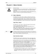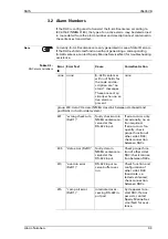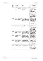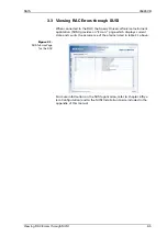
RAIS
056357/B
Principle of Operation
1-3
In dual-rudder systems, RACs for the port and starboard rudder are used
in a paired configuration. Each unit reads the feedback signal and drives
the analogue outputs for its own side. Through a crosslink, it also reads
the other unit’s digital output and produces a $--RSA sentence including
port and starboard rudder angles according to IEC 61162 (NMEA 0183).
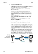
Figure 1-2:
RAIS with 2 RACs for
d
ual-rudder system
1.3 Principle of Operation
To attain an ISO 20673 compliant calibration accuracy for all RAIs con-
nected, the RAC applies calibration as part of the A/D conversion of the
analogue feedback signal as well as of the D/A conversion for each ana-
logue output.
An input calibration table maps the feedback input voltage to the corre-
sponding rudder angle for a number of significant rudder positions.
The actual feedback voltage is thus converted to a digital rudder angle
value and automatically corrected according to the stored calibration
table. This compensates for possible misalignment of the feedback unit
and non-linearity of the feedback potentiometer.
The corrected digital value forms the reference for both the serial data
output and the subsequent conversion to the six separate analogue out-
put voltages.
An output calibration table maps the digital rudder angle values to cor-
responding sets of analogue output voltages. This individually compen-
sates for the non-linearity, range variation and zero-offset of the
connected RAIs.
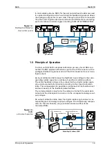
Figure 1-3:
RAIS
:
principle of operation
PORT
X
X
STB
PORT
X
X
STB
port side RAC
stbd. side RAC
VDR
port + stbd.
rudder angles
Rudder Angle Calibrator (RAC)
data formatting
output calibration
input calibration
A/D conversion
D/A conversion
A
D
x
y
D
A
x
y
$...
RUDDER
X
Summary of Contents for Rudder Angle Indicator System
Page 18: ...056357 B RAIS 1 10 Declaration of Conformity...
Page 20: ...056357 B RAIS 2 2 Normal Operational Mode...
Page 26: ...056357 B RAIS 3 6 Viewing RAC Errors through SUSI...
Page 28: ...056357 B RAIS 4 2 Maintenance by Service Personnel...
Page 58: ...056357 B RAIS 7 4 General Troubleshooting Instructions...
Page 64: ...056357 B RAIS 8 6 Replacing Alarm Output Relays...
Page 95: ......
Page 96: ......
Page 97: ......
Page 98: ......
Page 99: ......
Page 100: ......
Page 101: ......
Page 102: ......
Page 103: ......
Page 104: ......
Page 105: ......
Page 106: ......
Page 107: ......
Page 108: ......
Page 109: ......
Page 110: ......
Page 111: ......
Page 112: ......
Page 113: ......
Page 114: ......
Page 115: ......


