RAIS
056357/B
In- and Output Calibration
6-13
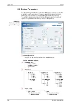
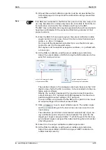
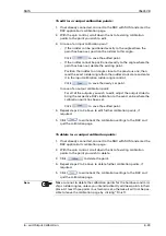
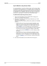
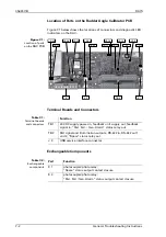
Figure 6-2:
Controls on the RAC
calibration page
1
Input Calibration Controls:
Rudder Angle dial and spin box
Calibration Point spin box
Delete and Save buttons
1
Output Calibration Controls:
Rudder Angle Indicator dial and spin box
Calibration Point spin box
Output Digit sliders and spin boxes
Delete and Save buttons
2
2
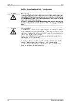
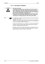
Note
Accessing the calibration page puts the Rudder Angle Calibrator into a
special calibration mode. In this mode, the analogue output voltages do
not correspond to the actual rudder angle but are determined directly by
the settings of the output calibration controls. Serial output of the rudder
angle is disabled in the calibration mode.
Summary of Contents for Rudder Angle Indicator System
Page 18: ...056357 B RAIS 1 10 Declaration of Conformity...
Page 20: ...056357 B RAIS 2 2 Normal Operational Mode...
Page 26: ...056357 B RAIS 3 6 Viewing RAC Errors through SUSI...
Page 28: ...056357 B RAIS 4 2 Maintenance by Service Personnel...
Page 58: ...056357 B RAIS 7 4 General Troubleshooting Instructions...
Page 64: ...056357 B RAIS 8 6 Replacing Alarm Output Relays...
Page 95: ......
Page 96: ......
Page 97: ......
Page 98: ......
Page 99: ......
Page 100: ......
Page 101: ......
Page 102: ......
Page 103: ......
Page 104: ......
Page 105: ......
Page 106: ......
Page 107: ......
Page 108: ......
Page 109: ......
Page 110: ......
Page 111: ......
Page 112: ......
Page 113: ......
Page 114: ......
Page 115: ......


