Page
14
of
98
118157-001 Rev C
XRV225kV Overview
:
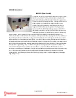
XRV225 (Front Panel)
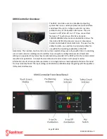
The XRV225 front panel uses the same LED Indicators
as the XRV160 showing the status of the Generator.
Green Indicators signify normal operational mode
while red indicators signify a fault condition. A fault
or red indication prevents high voltage operation.
Fault conditions are “latched” meaning that a reset
must be employed before re-starting the generator.
Once the fault clears, the red indicator will
extinguish. Additionally, fault status and ready
conditions are monitored from the I/O connector on
the rear panel and the GUI Interface software. A
removable air filter keeps dust and dirt from entering
the chassis.
XRV225 Front Panel Indicators
Summary of Contents for XRV Sub-system
Page 1: ...SPELLMAN HIGH VOLTAGE XRV SUBSYSTEM INSTALLATION MANUAL ...
Page 13: ...Page 13 of 98 118157 001 Rev C XRV 160kV Overview 400Vac 3Ø Input ...
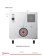
Page 17: ...Page 17 of 98 118157 001 Rev C XRV225kV Overview XRV225 400Vac 3Ø 6kW Unit ...
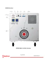
Page 21: ...Page 21 of 98 118157 001 Rev C XRV450 Overview XRV450 Bipolar Cathode Generator ...
Page 22: ...Page 22 of 98 118157 001 Rev C XRV450 Overview XRV450 Bipolar Anode Generator ...
Page 28: ...Page 28 of 98 118157 001 Rev C XRVC Controller Overview XRVC Controller Rear Panel Detail ...
Page 51: ...Page 51 of 98 118157 001 Rev C System Grounding Detail and HV Cable Connections ...
Page 66: ...Page 66 of 98 118157 001 Rev C ...
Page 67: ...Page 67 of 98 118157 001 Rev C Power Source Connections Unipolar Basic ...
Page 68: ...Page 68 of 98 118157 001 Rev C Power Source Connections Unipolar Basic ...
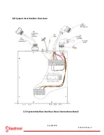
Page 72: ...Page 72 of 98 118157 001 Rev C Power Connections I O System Interface Box ...
Page 76: ...Page 76 of 98 118157 001 Rev C Main Input Power Connections I O System Interface Box ...
Page 77: ...Page 77 of 98 118157 001 Rev C I O Subsystem Interface Box System Diagram ...
Page 89: ...Page 89 of 98 118157 001 Rev C X Ray Tube Filament Calibration Setup ...


