background image

12 


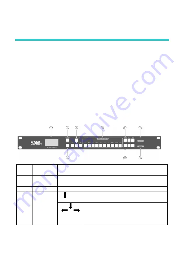
Front panel 

        The  Front  Panel  of  the  video  processor  uses  a  friendly  human  machine  interface  and 

clear and simple LCD menu displaying. The default menu displays the operation modes of the 

video processor for you, and you can use the main menu to set detailed parameters. The panel 

provides  the  most  frequently  used  shortcut  keys  with  LED  indicator  inside  (except  menu 

operation keys) to indicate the operation mode of the current function. 

        Among  the  input  shortcut  keys  of  “INPUT  SELECTION”,  press  a  key,  and  two 

indication modes may occur. When the indicator is flashing, it indicates there is no signal or 

no signal connection is detected; when the indicator is lit up, it indicates the signal connection 

is normal.   

The following figure shows the Front Panel:   


No. 

Name   

Description   


LCD 

Used to display the menu and current information. 


EXIT\ 

MENU 

Main  menu  or  exit.  In  the  main  menu  mode,  when  it  is  pressed, 
the system will return to the previous menu. 


ENTER 

Confirmation key 


Direction 

keys 

AUTO 

In  the  Default  menu,  the  input  VGA  video 
displaying can be positioned automatically. 


Down operation key 


In  the  Default  menu,  the  brightness  of 

videosoutput can be adjusted. Left: -; right: + 

Summary of Contents for LVP-1000

Page 1: ...LED Video Processor User Manual Model LVP 1000 1000S ...

Page 2: ...0 Installation of LED Transmission Card 11 Front panel 12 Menu 14 Default Menu 14 Main Menu 16 Structure of Main Menu 17 Function description 18 Output Resolution Setup 18 Crop 19 Signal Connection 19 Crop Setup 20 PIP Mode 21 Keying Mode 22 Seamless Switch 23 Test Patten 23 Preset Mode 24 Mult device 25 Multi device Connection 26 Audio Switching 28 troubleshooting 29 ...

Page 3: ...t to change without notice Unless specifically agreed this Manual is for guidance only No statement or information in this Manual constitutes guarantee in any form About This Manual Read this Manual carefully before using this device For persons who need to purchase the accessories to this device This Manual also provides the instructions on how to use such accessories If this Manual provides the ...

Page 4: ...redit VGA and XGA are the registered trademarks of IBM VESA is the trademark of Video Electronics Standards Association The HDMI logo and High Definition Multimedia Interface are the trademarks of HDMI Licensing LLC ...

Page 5: ... an environment where the temperature changes suddenly to prevent condensation Never use the device in an environment with excessive dust or high humidity Use the device in an environment with the ambient temperature from 10 to 40 and relatively humidity of 90 or below Never expose the device to a place where accidental collision or vibration may occur Consolidate the device when it is to be used ...

Page 6: ...he AC power connector to supply power to this device Network cable 1 pcs Universal network cable used for communication between devices and for debugging DVI cable 1 pcs Used to connect the signal source to the DVI input port of the device or connect the DVI output port of the device to the LED transmission card Φ5 18 Copper Pillar 4PCS M3 6 Round Head Screw 4PCS Used to fix the LED sending card ...

Page 7: ...e for the user purchasing or using the device Qualified Certificate The certificate that proves the product passes the strict quality inspection Warranty Card Product after service recording card with which the after service provided by the Company can be enjoyed within the warranty period ...

Page 8: ...es Video Processor supports signal cascade Through a simple fusion device ultra high resolution display can be realized without the purchase of expensive fusion controller All connected machines can be controlled with one key and it is more convenient in the splicing mode The seamless Switch quick switching and fade in fade out effects are provided to enhance and present demonstration pictures of ...

Page 9: ...wn the resolution conversion of signals with various resolutions and is equipped with the professional ACC and ACM video processing engine to give you completely new visual enjoyment LVP1000 has 7 video input interfaces and 3 video output interfaces covering the currently most common video interfaces and SDI high definition camera interface A visual LCD interface and clear keypad backlight simplif...

Page 10: ...y input AUDIO INPUT Audio input Analog audio input AUDIO OUTPUT Audio output Analog audio output YPbPr Video input Y 1Vpp 3dB 0 7V Video 0 3v Sync 75 ohm Pb Pr 0 7Vpp 3dB 75 ohm 480i 576i 480p 576p 720p50 1080i50 1080p50 1080p50 1080p60 V Composite video input 1Vpp 3db 0 7V Video 0 3v Sync 75 ohm PAL NTSC PAL M N SECAM SD HD 3G SDI Video input 1080p 60 50 30 25 24 25 PsF 24 PsF 720p 60 50 25 24 10...

Page 11: ...DVI2 REMOTE RX RS232 receiving Communication port for multi machine cascade REMOTE TX RS232 transmission LED Sending Card position Positions for installing 2 LED sending cards Parameters of the Machine Weight 3 6kg Dimensions 4 4cm H x44cm W x28 5cm D 1U high width of the full rack The depth does not include the connector and handle The width does not include the rack lug The width is 48 3cm for a...

Page 12: ...nized treatment is used for the ports of the video processor with a box indicating the input ports and a box indicating the output ports The ports in the box filled with black color are output ports the port name containing LOOP indicates port loop out In an engineering program try to use HD interfaces such as HDMI DVI or SDI The figure below shows the common installation programs ...

Page 13: ...so as to install the transmission card of the corresponding brand 2 Install the LED transmission card fix it with the 4 screws supplied tighten the hexagonal bolt of the DVI interface and insert the 4PIN 5V power cable into the power socket of the transmission card as shown in the figure When the transmission card is installed install the baffle of the case ...

Page 14: ...ECTION press a key and two indication modes may occur When the indicator is flashing it indicates there is no signal or no signal connection is detected when the indicator is lit up it indicates the signal connection is normal The following figure shows the Front Panel No Name Description LCD Used to display the menu and current information EXIT MENU Main menu or exit In the main menu mode when it...

Page 15: ... Full video displaying CROP Multi device splicing partial video displaying PIP Picture in picture Keying The set PIP or Keying parameters are invoked for displaying Press the PIP key repeatedly to disable or enable the PIP function When the TEST and BLACK functions are activated the PIP function can t be used When the PIP function is activated the CUT and FADE functions can t be used EFFECT CUT Se...

Page 16: ...or better quicker and more intuitive operation The menu system of the video processor will be described in details below by combining the displaying on the LCD and the keys on the panel Default Menu After the device powered on the LCD will display the current state of the device as shown in the figure The meanings of the contents of the figure are as follows No Description The main channel is VGA2...

Page 17: ...put channel PIP channel PIP channel input mark Brightness Indicates the current brightness Full video output The signal full output is enabled Same as the FULL key Crop mode The video Crop mode is enabled PIP mode Indicates the current mode is PIP mode Keying Mode The Keying Mode is enabled Line feed connection Line feed mark Menu connection Next level menu connection symbol Interconnection mode T...

Page 18: ...press the EXIT MENU key the video processor will enter the main menu mode and the LCD will display the following screen Use the EXIT MENU AUTO and ENTER keys to select and adjust the various options IMGE CAP OUT PIP FUNC ADV ...

Page 19: ...et OUT PIP Resolution Width Height H Start V Start Reset PIP Mode Keying PIP Off Input Frame Color Frame Size Blender H Start V Start Width Height Reset Input Chroma Key FUNC Language Timeout Preset Test PAT Seamless Fade Time ADV Device No Multi Device RGB Range Keypad Lock System Info Reset All VGA Setup User CT Auto Adjust H Position V Position H Clock Clock Phase WXGA Mode Reset Color Temp Red...

Page 20: ...n Through the critical function description you can configure the video processor quickly to complete the installation and debugging Before setting the various functions check that the device has been correctly connected and the signal input is normal Output Resolution Setup When the device is installed you need to set the output resolution of the processor according to the resolution of the LED w...

Page 21: ...gnal Connection The Crop function uses one input signal splicing unit that is a channel can use a signal source only signal loop out or signal distribution input may be used and outputs video on the LED wall after processing Take the DVI input splicing as an example the connection method is shown in the figure Part 2 1024 768 Part 3 1024 768 Processor 3 Processor 2 Processor 1 DVI DVI Splitter DVI...

Page 22: ... parameters 3072 Part 2 1024 768 Part 3 1024 768 Processor 1 Processor 2 Processor 3 The above example shows that the H Total is the sum of the horizontal pixels of the various LED walls the V Total is the sum of the vertical pixels of the various LED walls these two parameters are the same in the various processors The Horizontal Total Pixels and Horizontal Total Pixels 3072 Vertical Total Pixels...

Page 23: ...echnology to display two programs on the same screen that is on the main screen being watched normally one or more compressed sub screens are inserted so that the user can monitor other channels while watching the main screen In the PIP mode the user needs to provide at least two channels of signal input and set the PIP menu accordingly Before using the PIP function the user should understand the ...

Page 24: ...cture colors of the PIP channel input The Keying function can be used in some simple special effect processing and caption adding The setup operation is simple Refer to the setup example Enter the Keying menu In the main menu select PIP Keying Parameter Setup set the Input to VGA and the Chroma Key to Black Tip Here the Chroma Key refers to the colors extracted including blue green red and black I...

Page 25: ... effect function can t be used To use this function disable the PIP function first The PIP function can be disabled in the main menu or with the PIP shortcut key Seamless Switch has two effects i e CUT and FADE CUT is instant Seamless and FADE is fade in fade out The time of fade in fade out can be set in the main menu select FUNC Fade Time Parameter Setup Test Patten After the LED wall is install...

Page 26: ...ncy of operations Each preset mode includes such parameters as signal channel mode displaying mode picture quality setup etc The saving and invocation of the preset mode are described below Saving of preset mode In the main menu select FUNC Preset Save Mode select any set of preset settings and press ENTER to save it Up to 4 sets of preset settings can be saved Invocation of preset mode On the Fro...

Page 27: ...d output of multiple video signals The advantage of Multi device interconnection is that when any device is operated the concatenated devices will act simultaneously The functions that can be realized include Switch of input signals INPUT SELECTION main channel selection Multi device template loading PRESET key Seamless Switch CUT and FADE keys VGA automatic positioning AUTO key Brightness adjustm...

Page 28: ... the figure Processor 1 Processor 2 Processor 3 About Setup and Operation After the devices are connected all interconnected devices should be set as follows Set Machine No Press the EXIT MENU key to enter the main menu select Advanced Machine No set the desired machine number and press the ENTER key The machine numbers must be different from each other otherwise interconnection can t be realized ...

Page 29: ...LACK Output black screen LVP 2000 does not have this function PRESET Invoke scenario mode including signal channel mode video quality setup etc CAPTURE Full video displaying partial video displaying Multi device video Crop FULL Full picture displaying CROP Multi device video splicing partial video displaying EFFECT CUT Seamless switch When the main channel is switched the video will not interlace ...

Page 30: ...e audio connection is in the External Sound Channel Input mode and the video is switched without changing the sound channel Sound Channel Following When the video is switched to HDMI the sound channel outputs HDMI audio when the video is switched to SDI the sound channel outputs SDI audio when the video is switched to V YPbPr VGA1 VGA2 or DVI the sound channel outputs external audio Audio Off Pres...

Page 31: ...displayed on the display normally and the video can t be displayed on the full screen or is blurred This can be solved through automatic positioning of VGA input signal When the current input source of the video processor sends effective VGA input signals press the AUTO key and the video processor will position the sampling parameter of VGA input signals automatically to make the VGA video clear a...

Page 32: ... of PIP is abnormal Check whether the PIP parameters are set correctly and reasonably The Seamless Switch function does not work Check whether the current mode is PIP mode Disable the PIP function No sound Check whether the input sound is normal whether the system is switched to the current sound channel and whether the audio amplifier is normal ...

Page 33: ...o t line 4 0 0 62 8 6 95 9 深 圳 市 杰 思 创 科 技 有 限 公 司 SHENZHEN SPEEDLEADER TECHNOLOGY CO LTD Tel 0755 26588939 Fax 0755 26586619 Post Code 518052 Address 6 F Bldg 78 Majialong Industrial Zone Nanshan District Shenzhen http www speedleader cn ...

Reviews: