CONTROLS AND INDICATORS
15
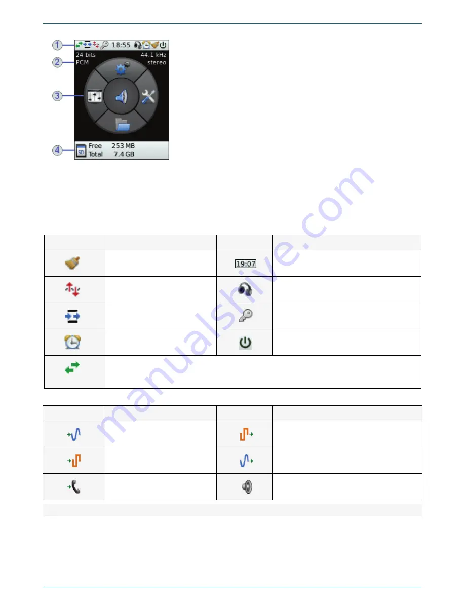
You can see the LCD and main menu of the system in the figure 21.
Figure 21 – LCD and main menu
There are four sections of the LCD:
1 – In that section, you can see icons, which show parameters of the current
working mode.
2 – In that section, you can see parameters of current recording format.
3 – In that section, you can see main menu of the device and its mnemonic
match to five navigation buttons (figure
2
, position
3
).
Press the proper navigation button to see parameters and commands of the
lower level of the menu in parts 2 and 3.
When you open the
Lines selection
menu, you can see icons of the currently
used inputs and outputs of the device.
4 – This part changes its content according to the working mode. Here, you
may see SD-card capacity (see figure
9
); recording process and time (see
figure 18); amplification value during the recording (see figure 20) or
playback (see figure 19).
In the tables 3 and 4, you can see the information about icons, which are located in sections
1
and
3
and are used to indicate
parameters and working modes of the device.
Table 3 – Icons of the section
1
Icon
Description
Icon
Description
Batch noise reduction is on
Current time
Voice activation is on
Headphones connected
Point-to-point channel is on
PIN code protection is active
Timer is on
External power source connected
Switching the channels during the playback (monitor or file) to the left/right/mix. The option is
available only if the sound comes through headphones/built-in dynamic. To adjust that parameter
press volume control.
Table 4 – Icons of the
Lines selection
section
Icon
Description
Icon
Description
Recording from line input
Playing to lines of digital output
Recording from digital input
Playback to external lines of line output
Record from telephone line
Playback to headphones/built-in speaker
4.2.2
Indicators of the recording level
Indicators of the recording level (figure
2
, position
10
) are two rows of LEDs (light-emitting diodes) on the front panel of the
device. The glow of certain green LEDs indicates relative value of the recording level. The glow of the last two LEDs indicates
the exceeding of normal signal level and possible distortion of recorded signal.
Summary of Contents for ANF II
Page 78: ...Documentation version 06 01 07 2013 Software version ...
Page 79: ......
Page 80: ......


