background image

20


Membrane Cleaning 


For normal cleaning, the SC

-

3 Acid Cleaning Compound is used first, then the SC

-

2 Alkaline 

Cleaning Compound. If known bio

-

fouling is present (rotten egg smell) the SC

-

2 may be used 

first. Using hot water if possible, up to 120° (45C) is  recommended as it greatly enhances the 

ability of the cleaners to do their jobs.


If the history of the system is unknown or it has been left 

unpickled

” 

for an extended length of 

time and biological growth is present, it is recommended that the system is cleaned with SC

-

2, 

using an alternate source of unchlorinated fresh water before the system is run under pres-

sure. A simple test can be performed  to see if biological growth has occurred. Before running 

the system, remove the prefilters and examine their condition.  If the housings are full of smelly 

discolored water, the system was not properly stored. Install clean prefilters if they were bad. 

Next check the membrane. Attach the brine service hose and lead it to a bucket. Open the 

pressure relief valve one turn, and run the system for 30 seconds. Examine the brine water: if 

it

s discolored and smells bad, perform an SC

-

2 cleaning with an alternate source of unchlorin-

ated water before running the system pressurized. If the brine is fairly clean, the system can be 

purged, run normally, and checked for performance. Clean the membranes only if performance 

is reduced.


Heating the water is preferable. One way to do this is to find a camp stove and use a large 

stainless steel pot to heat the solution in. The cleaning solution throughout the system will heat 

as it circulates in and out of the pot. An alternative is to heat the one or two gallons of initial 

water to 120° on the main stove before mixing in the cleaner and circulating it into the system. 

Periodically stop and reheat the solution.


Perform the cleaning procedures and then test on a normal feed water supply.


The membranes need to be cleaned only when feed pressure begins to rise due to fouling or 

the product quality degrades. The leading cause of fouling is from biological growth that occurs 

when the system is left unused without flushing or pickling. Fouling from mineral scaling can 

happen during operation under certain source water conditions, and from rust. Monitor the 

product salinity and feed pressure for higher than normal readings for the existing conditions. 

Other conditions can cause high pressure such as cold feed water or clogged filters

Low product flow is usually due to low voltage, a damaged well pump or Clark Pump problems. 

Look for all other causes before cleaning the membrane as excessive cleaning shortens mem-

brane life.


There are two types of cleaners: acid and alkaline. The acid cleaner (SC

-

3) will remove mineral 

scaling. The alkaline cleaner (SC

-

2) is used to remove biological by

-

products, oil, and dirt parti-

cles that get past the pre

-

filter. If membrane performance is reduced and they have not been 

pickled

” 

recently, cleaning with both chemicals is recommended. The acid cleaner should be 

used first followed by the alkaline cleaner.  If the membrane fails to respond to both cleanings, 

this is an indication of another problem with the system, or that it is time to replace the mem-

brane. Contact Spectra Watermakers before removing a membrane.


Aquifer Membranes maintenance and Cleaning


Summary of Contents for AQUIFER 360 EXPEDITION

Page 1: ...FER 360 EXPEDITION FLIGHT READY With Solar Power OWNER S MANUAL Katadyn Desalination LLC Manufacturer of Spectra Watermakers PH 415 526 2780 FX 415 526 2787 www spectrawatermakers com Revised October...

Page 2: ...2...

Page 3: ...ltage kit 7 Well Pump Connections 11 Operation New Systems Start Up and Testing 11 Operation 14 Maintenance 15 Service Maintenance Long Term Storage 17 Winterizing 19 Membrane Cleaning 21 Suggested Sp...

Page 4: ...The small installation parts are listed on the kit list Warning We will not be held responsible for shortages and or freight damage that are not reported within thirty days of the ship date Getting St...

Page 5: ...where any water spilled during filter changes will not be a problem If the unit is to be installed in a mobile vehicle it should be strapped it down with webbing through the handles to keep it in plac...

Page 6: ...pply 5 micron filter with gauge Brine discharge hose Feed Water connection Connect to pumps Feed water hose connects directly to the feed pump con nector Case for pumps and hoses Pump connector hose c...

Page 7: ...ottom of a tank Make sure that there is no possible re striction in this piping Note The product flow meter displays the flow per hour In normal operation the flow will go up and down as the Clark Pum...

Page 8: ...and the power being used When the batteries are fully charged the input Amps will drop to below 1 Note that the load will disconnect the pumps will stop if the battery voltage the battery voltage drop...

Page 9: ...nd then connect the remaining plugs to the cables from the power supply The solar panels work best when the sun is di rectly over them so it will help if the panels can be set up at an angle so they a...

Page 10: ...the dust caps in place on the plugs to keep them clean as clean connectors work much better When plugged in the connection is water resistant not water proof so be sure it is nev er submerged in wate...

Page 11: ...op tional but recommended as it will help the prefilters to last longer Note that the float foam can also be removed for placing the pump down a bore hole Tie the bag onto the pump using a bow and the...

Page 12: ...storage chemicals Ensure that the pressure relief valve is open 1 2 turn Connect to a power source 100 to 240vac 12 or 24vdc using the marked terminals 2 Plug the feed water pump into the power cable...

Page 13: ...until you have filled your tank or have made enough to meet your re quirements plus 5 gallons for flushing the system 7 Make about 5 gallons of water one of the waterproof bags or a bucket to be used...

Page 14: ...lter bowl as shown If the filter bowl gets stuck have someone tap on the housing actually hit the label with a hammer while applying pressure with the wrench 2 If the pressure drops and the filter is...

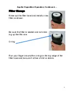
Page 15: ...Change Rinse out the filter bowl and install a new filter as shown Be sure the filter is seated and not stick ing up like this one O ring Run your finger around the o ring on the top edge of the filt...

Page 16: ...o the system that pre vents biological growth This procedure requires de chlorinated water Spectra SC 1 a special storage compound used by the US Navy It is formulated to be compatible with the modern...

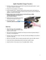
Page 17: ...1 2 turn counterclockwise 6 Start and run the well pump to circulate the solution for about ten minutes 7 Stop the well pump Leave the pressure relief open Clean Up Drain hoses as much as possible so...

Page 18: ...hose 6 Stop the well pump Connect the brine service hose to the brine outlet on the Aq uifer case and place it in the bucket 7 Start the well pump and circulate the re maining antifreeze for a few mi...

Page 19: ...leave dirty filters in the machine during long idle periods as biological con tamination could result To service the filter swing the housing out of the case open the hous ing using the supplied filt...

Page 20: ...he system will heat as it circulates in and out of the pot An alternative is to heat the one or two gallons of initial water to 120 on the main stove before mixing in the cleaner and circulating it in...

Page 21: ...the bucket so the water in the bucket will circu late through the system and go back into the bucket 4 Make sure that the pressure relief valve is OPEN un pressurized 5 Pour one packet of the cleaning...

Page 22: ...ings for filter hous ing Spectra Watermakers parts list Part Number SC 1 STORAGE COMPOUND KIT CHEM SC1 SC 2 ALKALINE CLEANING COMPOUND KIT CHEM SC2 SC 3 SCID CLEANING COMPOUND KIT CHEM SC3 SUPPORT KIT...

Page 23: ...ogged Service pre filter and strainer Low water production Low pressure Pressure relief valve partially open Worn pump head Close valve Check flow should be 1 5 GPM from brine discharge with pressure...

Page 24: ...in flush water They must be of proper specification to be suitable There is no test for chlorine dam age except the process of elimination of other causes DIRTY OR SCALED membranes A dirty foreign mat...

Page 25: ...t or the ball will fall out and then lever the top cap off It is hard to see but there is a small notch in the back of the cap where you can put the small screwdriver and begin to pry the cap off The...

Page 26: ...y an hour or so each day will probably need to have the filters changed due to odor before they are dirty enough to restrict water flow Prefilters can be cleaned We recommend that you have three sets...

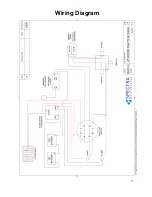
Page 27: ...27 Wiring Diagram...

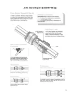
Page 28: ...28 John Guest Super Speedfit Fittings...

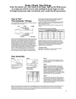
Page 29: ...be Fittings Note the plastic nut only needs to be finger tight as the fitting uses an o ring seal and the nut is only holding the grab rings in place Overtightening may strip the threads and render th...

Page 30: ...ck of the Clark Pump have cap tive nuts and washers which compress the O rings without turning the entire fitting If a tube fitting leaks it can sometimes be resealed by just tightening You must use t...

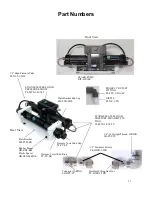
Page 31: ...PV ER 1 2 High Pressure Tube PL NLT 1 2HP Part Numbers Stainless Fitting Hex Nut PL HWR 1 2HN 1 2 Stainless Ferrule PL HWR 1 2FR Connector O RING SO HPP CT 3 4 16 Straight Thread O RING SO FT STF STA...

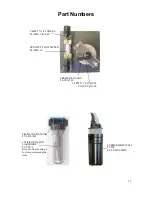
Page 32: ...W METER PL FMT 10 PREFILTER HOUSING FT FTH 10H 5 MICRON FILTER CARTRIDGE FT FTC 5 Note the clear housing is for low pressure applica tions PRESSURE GUAGE PL PSG 2 5L 1 4FPT X 1 4 TUBE EL PL FTE 1 4X1...

Page 33: ...33 HP TB VEB B HP TB VB HP TB VEB A HP TB BV HP CB CB7 HP CYL SST HP CYL R HP CYL EC HP CYL CCA Not used Clark Pump Assembly...

Page 34: ...34 HD CPS 5 16X3 KIT HP 10VSA HP TB ARP SO HPP AR1 SO HPP RV HP TB BV HD CPS 5 162 75 SO HPP SP HP TB VSP HP TB SR SO HPP VB SO HPP PLP SO HPP VP...

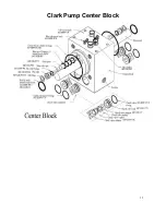
Page 35: ...35 Clark Pump Center Block...

Page 36: ...36 PL MTS 3 8X1 2S HP CYL SST HP CYL CCA SO HPP ECCB HP CYL EC HP CYL R HP CYL PT Clark Pump Cylinder Assembly...

Reviews: