


29
CCX 70
V1.1 | 29 April 2016
Chapter 7 – Technical Details
This chapter contains an overview of the features on the front and rear panels of the CCX 70,
including pin assignments of the electrical connectors. It also contains information about the
internal components and construction of the instrument.
7.1
Front Panel
There is no power switch on the front panel of the CCX 70—power is controlled by the UXC
1000.
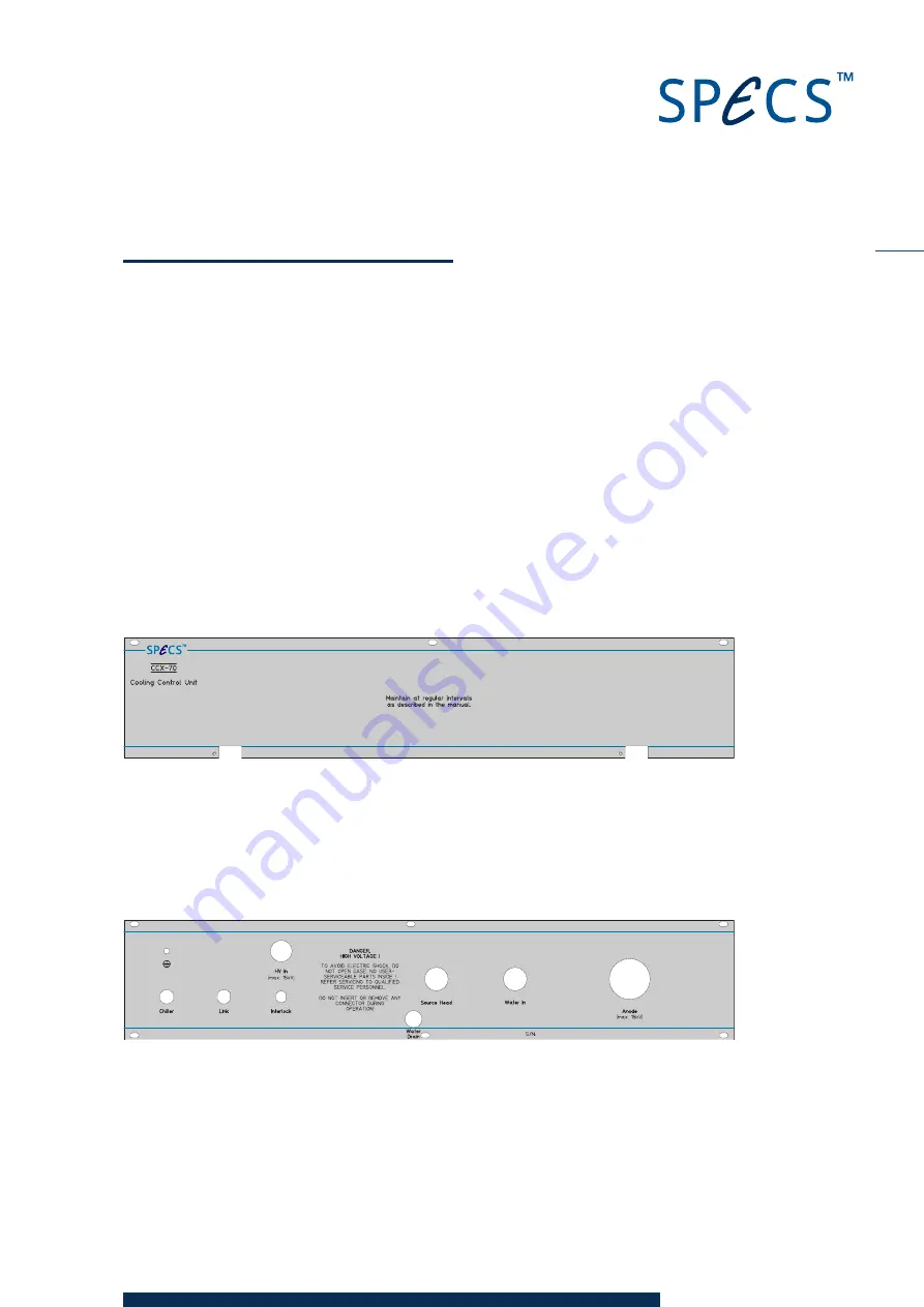
The only feature on the front panel is the service area. This is held in place by two screws. The
service area opens on hinges, providing easy access to the cathode filters. The cleaning pro-
cedure is described in "Cleaning the Internal Filters" on page 23. There is a switch fitted to the
panel which acts as an interlock. The power is switched off when the panel is open.
Figure 8: Front panel
7.2
Rear Panel
The rear panel is fitted with all electrical and water connections, as well as a water drain. The
figure and sections below describe the features. Pin assignments of the connectors are also
included.
Figure 9: Rear panel
HV In
This cable connects to the HV Out on the UXC 1000. It routes the voltage with the anode cooling
water through the Anode conduit.
Summary of Contents for CCX 70
Page 1: ...CCX 70 Cooling Water Controller User Manual V1 1 29 April 2016...
Page 4: ...CCX 70 V1 1 29 April 2016 7 4 Interior Details 32 7 5 Specifications 33 Index 35 iv...
Page 8: ...CCX 70 V1 1 29 April 2016 This page intentionally left blank 4...
Page 13: ...9 CCX 70 V1 1 29 April 2016 Figure 1 Connection scheme for water cooling...
Page 14: ...CCX 70 V1 1 29 April 2016 This page intentionally left blank 10...
Page 22: ...CCX 70 V1 1 29 April 2016 This page intentionally left blank 18...
Page 26: ...CCX 70 V1 1 29 April 2016 This page intentionally left blank 22...
Page 32: ...CCX 70 V1 1 29 April 2016 This page intentionally left blank 28...
Page 38: ...CCX 70 V1 1 29 April 2016 This page intentionally left blank 34...
Page 40: ...This page intentionally left blank CCX 70 V1 1 29 April 2016 36...


