background image

Page 21

HF-100 Users Guide

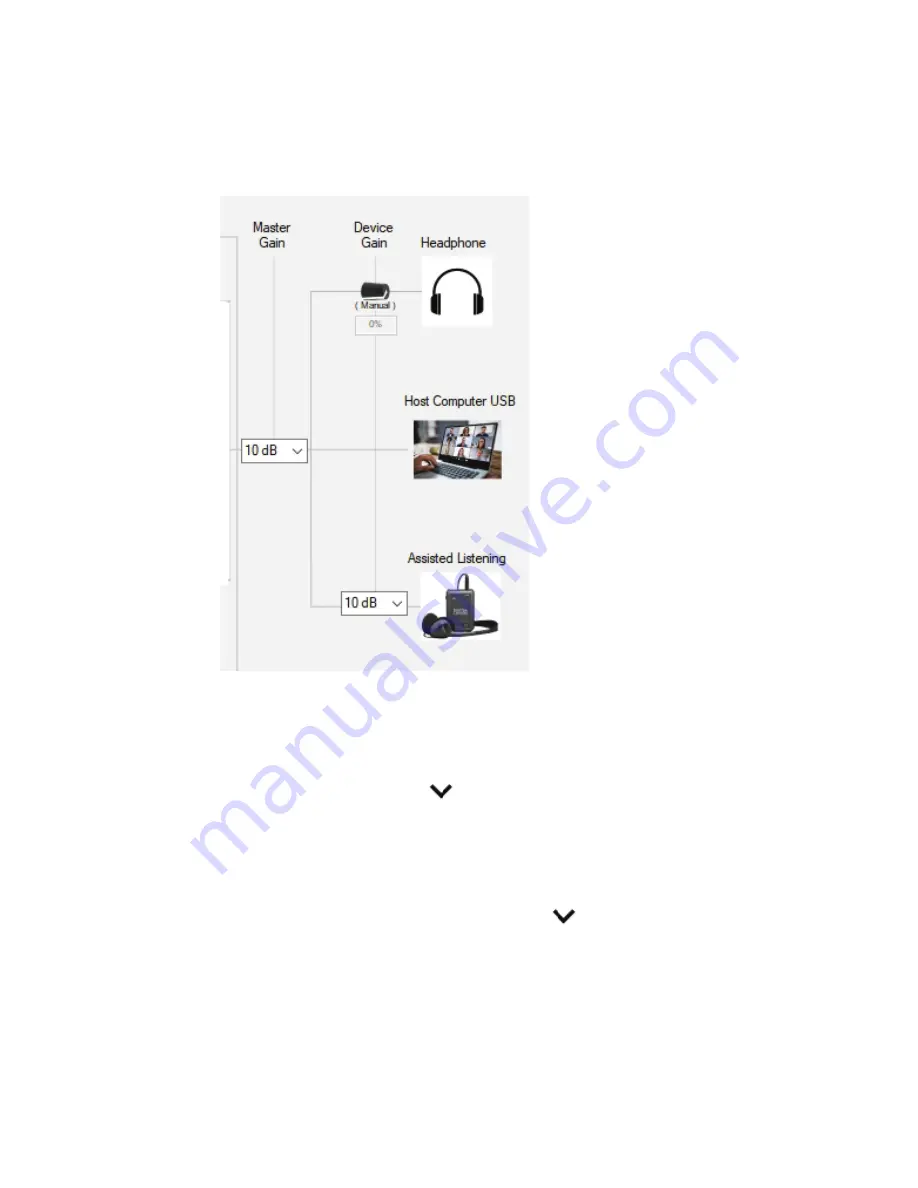
Output Device Settings

Output Device Settings

This sec  on deals with the gain levels of the audio being sent to HF-100’s output devvices, a  er 
the Bandpass and DRC audio process blocks.

Master Gain

Master Gain

The Master Gain se   ng is a gain adjustment that is applied a  er all the other DSP processing 
blocks. This gain se   ng e

 ects the volume level being heard by the remote users via USB host 

computer, assisted listening / line output port, and the headphones. Click in the master gain box 
or on the down poin  ng carat           to adjust the gain.

Assisted Listening  / Line Output Gain

Assisted Listening  / Line Output Gain

The Assisted Listening Gain se   ng is a gain adjustment that is applied a  er the master Gain and 
only applies to line output port. This gain se   ng is addi  ve to the gain level a  er the master 
gain; therefore, adjust the master gain before making this adjustment. Click in the Assisted 
Listening gain box or on the down poin  ng carat           to adjust the gain.

Summary of Contents for Hiflex HF-100

Page 1: ...PDATED September 2021 PN DOC 000032 01a SP Controls Inc 930 Linden Avenue South San Francisco CA 94080 Toll Free in US 877 367 8444 Tel 650 392 7880 Fax 650 392 7881 info spcontrols com HYBRID CONFERENCING SOLUTIONS HiFlex ...

Page 2: ...m 2021 SP Controls Inc All rights reserved SP Controls Inc 930 Linden Avenue South San Francisco CA 94080 No part of this document may be reproduced or transmi ed in any form or by any means electronic or mechanical for any purpose without the express wri en permission of SP Controls Inc Under the law reproducing includes transla ng into another language or format As between the par es SP Controls...

Page 3: ...ed Microphones 10 Phantom Power 10 Phantom Power Dip Switch Settings 10 Assisted Listening Devices 10 Connecting USB Audio to Host Computer 11 Selection of Microphone by Operating System 12 Selection of Microphone by Video Conferencing Software 12 Power 12 Software Configuration 13 Connecting to the HF 100 Update Port to Host PC 13 Installing the Software 13 Application Overview 14 Microphone Inpu...

Page 4: ... Bandpass Filter 17 Dynamic Range Compression DRC Settings 17 General Charting Overview 18 Threshold 1 and Threshold 2 18 Compression Ratio 0 19 Compression Ratio 1 19 Compression Ratio 2 19 Offset Region 1 19 Offset Region 2 19 Energy 19 Attack Decay 19 Presets 20 Output Device Settings 20 Master Gain 21 Assisted Listening Line Output Gain 21 ...

Page 5: ...Page 5 HF 100 Users Guide This page is inten onally blank ...

Page 6: ...ain adjustments Designed specifically for classroom lecture halls and conference facili es the HF 100 is a valuable and unqiue tool that allows remote par cipants in a conference call to clearly hear those speaking in the host room Getting to Know the HF 100 Getting to Know the HF 100 The graphic below points out key a ributes of the HF 100 Back View Back View Front View Front View Introduction Ph...

Page 7: ...applied Assisted Listening Connec on The Assisted Listening Connec on Line Output is used to send combined near side and remote a endee audio to an assisted listening transmi er The gain or volume level of this port may be adjusted using the HF 1xx Applica on Se ngs so ware See the sec on So ware Configura on for more informa on on this gain adjustment Applica on Connec on Reset This connec on is ...

Page 8: ...SP Controls Manufacturer Model Pattern Audix M55 Series Ceiling Cardioid High Output 18 52V Phantom Power 8 10 Above Surface 4 per 30 x30 room Microphone Spacing Microphone Spacing General Strategy General Strategy From a technical standpoint one must visualize a polar pa ern as the pickup on a microphone However our Audix representa ve simplied the design by imagining a 10 diameter bubble on 8 10...

Page 9: ... Host Computer should be routed to the inroom speakers This is done so remote par cipants to the video conference can clearly hear remote par cipants The placement of the speakers is essen al to reduce any poten al feedback from the microphones Speaker Placement Speaker Placement Speakers should be installed between microphone placements Pay par cular a en on to the pickup pa ern of the microphone...

Page 10: ...y means of a DIP piano style switch Press down to enable phantom power on the switch which corresponds to the microphone connec on which needs the power In the image above all microphones have phantom power disabled Assisted Listening Devices Assisted Listening Devices O en schools are required to provide ADA Assisted Listening devices to augment the sound reinforcement in the room for those stude...

Page 11: ...ade to the bandpass dynamic response compression and gain se ngs The control knob to the le of the headphone port is used to adjust the volume Connecting USB Audio to Host Computer Connecting USB Audio to Host Computer To connect the HF 100 Audio Bridge to a Host Computer one must first make the hard wire connec on This requires a USB Type C to USB Type A cable in most cases In some cases the Host...

Page 12: ... Selec on of Microphone by Video Conferencing So ware Zoom The microphone can be selected while in a conference call or by changing the default microphone Here is how you change the default microphone so you only need to do this once Zoom Se ngs Audio then click on the Microphone selec on pull down Google Meet Here is how you change the default microphone so you only need to do this once Look for ...

Page 13: ...r when you plan to upload new firmware to the HF 100 Installing the Software Installing the Software To install the HF 1xx Applica on Se ngs program download and run the HF 1xx Applica on Se ngs setup u lity from the SP Controls HF 100 product page Once the installa on has fin ished you will see an HiFlex SP icon located on your desktop The so ware does not require a con nuous Internet connec on t...

Page 14: ...se microphones DSP audio processing effects on the mixed microphone signals and the output sec on that adjusts certain gain levels as signals leave the HF 100 Microphone Inputs Microphone Inputs In this sec on microphones are enabled or disabled gain levels are set for individual micro phones and the mixed signal is adjusted as necessary before the audio processing block MIC INPUTS AUDIO PROCESSING...

Page 15: ...gain se ngs can be heard in real me in the output devices Microphone Input Settings Microphone Input Settings Enabling Disabling Microphones Enabling Disabling Microphones As shown in the graphic above there is a small checkbox located to the upper le of each microphone When the checkbox is checked the microphone is acƟve and part of the mix When the checkbox is not checked the microphone is ignor...

Page 16: ... are two primary audio processing blocks in the HF 100 One is the Bandpass Filter module and the second is the Dynamic Range Compression DRC Bandpass Filters Bandpass Filters The Bandpass Filter module is comprised of two dis nct filters high and low A frequency is specified for each filter As shown in the graphic above the high bandpass filter is denoted in Red and the low bandpass filter in Gree...

Page 17: ... field or press the tab key to affect the change Dynamic Range Compression DRC Se ng Dynamic Range Compression DRC Se ngs Dynamic range compression DRC is very different than a bandpass filter Instead of reac ng to frequencies the DRC reacts to the sound levels or averaged amplitude of sound Think of DRC like an automa c volume control knob that adjusts based upon the sound level the device is heari...

Page 18: ...e all frequencies an addi onal amount to limit possible clipping The a ack me tells how quick this will happen and the decay value explains how long the sound level will remain a enuated before resampling the audio and returning to a new audio level Colors The black line is an indicator of unity gain That is if the system were set such that whatever comes into the DRC block is simply passed on to ...

Page 19: ...e black iden ty line In the example above at the Threshold 2 audio level the output will be the equal to the input dB minus this offset From a graphical standpoint the Threshold 2 inflec on point will occur exactly 16dB Offset Region 2 modifies the output gain for the en re range of possible audio input levels Satura on Zones Keep the blue line out of these areas This is a visual representa on of wh...

Page 20: ...e ngs to a known configura on Other presets are se ngs that solve specific problems or define a par cular set for a classroom or conference room configura on Click in the Preset box or on the appropriate down poin ng carat to select the preset Attack Time Decay Time time Decay Time time Attack Time During Compression During Expansion Gain Increase Gain Decrease ...

Page 21: ... the remote users via USB host computer assisted listening line output port and the headphones Click in the master gain box or on the down poin ng carat to adjust the gain Assisted Listening Line Output Gain Assisted Listening Line Output Gain The Assisted Listening Gain se ng is a gain adjustment that is applied a er the master Gain and only applies to line output port This gain se ng is addi ve ...

Page 22: ... 2021 SP Controls Inc All rights reserved SP Controls Inc 930 Linden Avenue South San Francisco CA 94080 info spcontrols com ...

Reviews: