background image

BIOS Setup Utility

64

SY-6BB

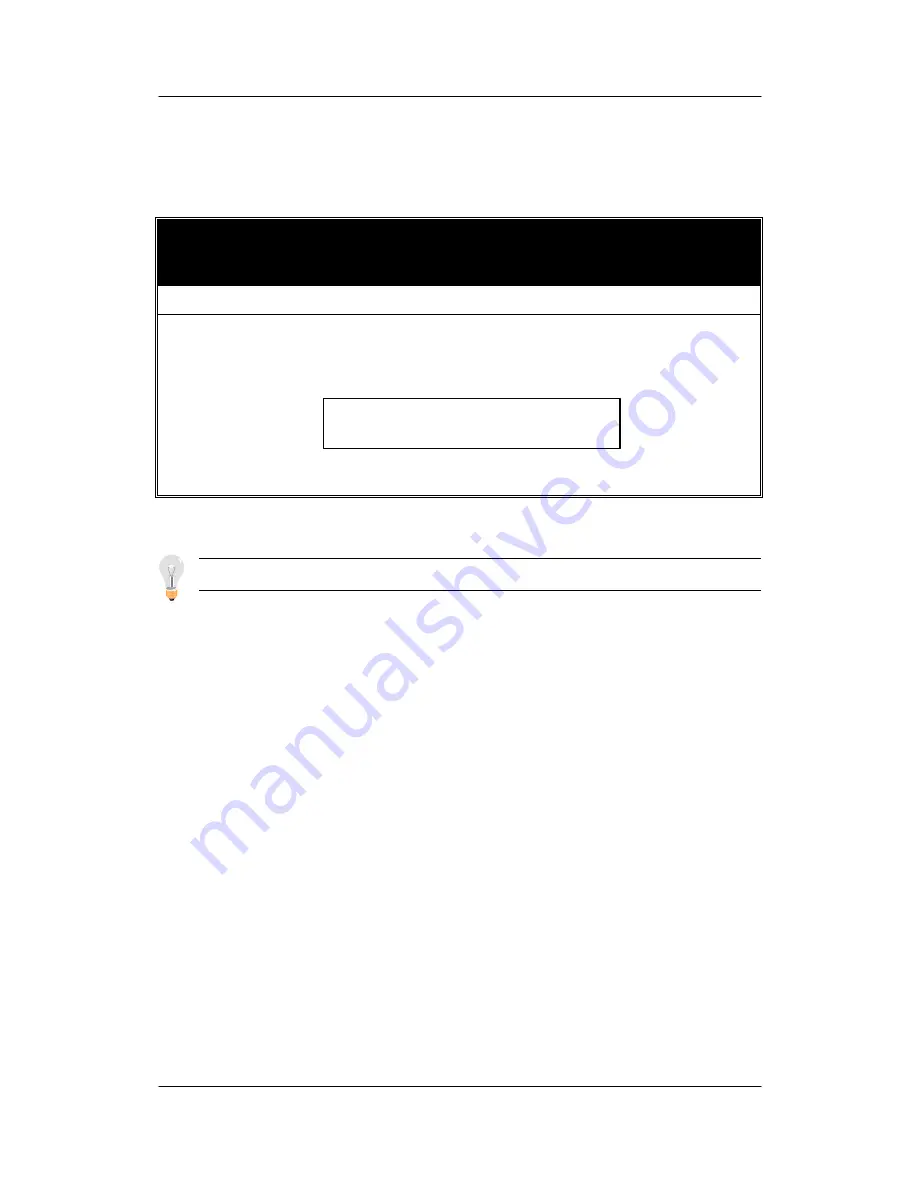
3-11  IDE HDD AUTO DETECTION

This Main Menu function automatically detects the hard disk type

and configures the STANDARD CMOS SETUP accordingly.

ROM PCI/ISA BIOS

CMOS SETUP UTILITY

AWARD SOFTWARE, INC.

HARD DISKS

TYPE

SIZE

CYLS HEAD

PRECOMP

LANDZ

SECTOR

MODE

Primary Master
Primary Slave
Secondary Master
Secondary Slave

:  AUTO

:  None

:  None

:  None

0

0

0

0

0

0

0

0

ESC :

0

0

0

0

Skip

0

0

0

0

0

0

0

0

0

0

0

0

AUTO

- - - -

- - - -

- - - -

Note: This function is only valid for IDE type of hard disk drives.

Do you accept this drive C (Y/N)? _

Summary of Contents for SY-6BB

Page 1: ...SY 6BB Mainboard Pentium II processor 66 100MHz supported 82440 BX AGP Set Mainboard AT Form Factor User s Guide Technical Reference...

Page 2: ...f the product described within it at any time without notice and without obligation to notify any person of such revision or change The information contained in this manual is provided for general use...

Page 3: ...OWER ON BY KEYBOARD FUNCTION JUMPER JP5029 2 3 AUTO DETECT CPU VOLTAGE 29 2 4 CPU TYPE CONFIGURATION 30 2 5 MEMORY CONFIGURATION 32 2 6 MULTI I O ADDRESSES 33 2 7 MAKING CONNECTIONS 33 CHAPTER 3 BIOS...

Page 4: ...SB LINK Intel 82371 EB Intel 82443 BX AGP Slot CPUFAN PCI Slot 1 PCI Slot 2 PCI Slot 3 ISA Slot 1 ISA Slot 2 ISA Slot 3 DIMM 1 DIMM 2 DIMM 3 IDE 1 IDE 2 Slot 1 for Pentium II Processor PRT 1 COM 1 CO...

Page 5: ...DIMM Module Support 8 128MB DIMM in each Bank Supports ECC configuration BIOS System BIOS built in Award BIOS Plug and Play function PCI Slots 3x 3 x 32 bit Bus Mastering Slots AGP Slot 1x 1 x 32 bit...

Page 6: ...OS Clear Jumper JP44 WOL Wake On LAN 3 pin Connector JP50 Power On by Keyboard Function Jumper SBLINK PCI Audio Card Connector DEFAULT SETTINGS CPU Pentium II 233 350 MHz Processor CPU Voltage Auto De...

Page 7: ...the installation successfully 1 Pentium II processor with built in CPU cooling fan boxed type Note This motherboard supports non boxed type CPUs The heavier CPU cooling fan requires the installation...

Page 8: ...on INSTALLATION GUIDE We will now begin the installation of the motherboard Please follow the step by step procedure designed to lead you to a complete and correct installation Step 1 CPU Installation...

Page 9: ...6BB 2 Position the Motherboard Locate Slot 1 on the motherboard and position the board in the direction as shown in the following figure Supporting Base Support Clip Screws x2 Retention Clip Latches...

Page 10: ...all the Supporting Base Insert the supporting base into the two holes adjacent to the two sets of screws previously installed Pay special attention to the directionality provided by the larger pinhole...

Page 11: ...8 SY 6BB 5 Install the Retention Clip Set the retention clip centered on Slot 1 and right on top of the two sets of screws along side Slot 1 as shown in the following figure Then tighten the four scre...

Page 12: ...tallation Guide 9 SY 6BB 6 Install the CPU Insert the CPU into the retention clip and lock the two latches on the sides of the CPU to secure the Pentium II processor in place as shown in the following...

Page 13: ...supporting base so that the CPU heat sink can seat on top of the supporting base as shown in the following figure 8 Insert the Latches Insert the two latches in the corresponding pinholes on the supp...

Page 14: ...ettings are changed through the BIOS Refer to Chapter 2 Hardware Setup and Chapter 3 BIOS Setup Utility for details on how to set the Pentium II processor frequency Step 4 DRAM Module Installation Thi...

Page 15: ...Installation The system supports 5 possible floppy drive types 720 KB 1 25 MB 1 44 MB 2 88 MB and LS 120 In addition this motherboard supports a 3 mode 720KB 1 25MB 1 44MB floppy commonly used in Japa...

Page 16: ...ush button cable into the 2 pin Reset connector on the motherboard Pushing the Reset button on the front panel will cause the system to restart the boot up sequence 3 Speaker Attach the 4 pin PC speak...

Page 17: ...ectly into the back panel KB connector For other serial PRT1 and parallel devices COM1 COM2 first install the external connectors that come with your motherboard on the computer case then plug the oth...

Page 18: ...th 9 pin flat cable Plug the 9 pin end of the flat cable into the COM1 or COM2 serial connector on the motherboard as shown in the figure below then fix the external 9 pin or 25 pin connector to the r...

Page 19: ...e 25 pin end of the flat cable into the PRT1 parallel connector on the motherboard as shown in the figure below then fix the external 25 pin connector to the rear panel of the computer case Then plug...

Page 20: ...PS 2 Mouse Attach the mouse cable to the 6 pin male PS 2 mouse connector on the motherboard to enable PS 2 mouse function 5 Universal Serial Bus USB1 USB2 This motherboard provides two USB ports for...

Page 21: ...nnected computer through the LAN card Please install according to the following pin assignment 2 Infrared IR Plug the 5 pin infrared device cable to the IR connector This will enable the infrared tran...

Page 22: ...stall according to the following pin assignment 2 Chassis Cooling Fan Some chassis also feature a cooling fan This motherboard features a CHAFAN connector to provide 12V power to the chassis fan Conne...

Page 23: ...of VGA cards into the PCI or ISA expansion slots according to card specifications Step 12 PCI Audio Card Some soundcards require a DMA channel Attach the 5 pin cable from the PCI Audio card to the SB...

Page 24: ...a power good signal Make sure the ATX power supply can take at least 10mAmp load on the 5V Standby lead 5VSB to meet the standard ATX specification Note on KB Wake Up Function Power Requirements If yo...

Page 25: ...turned off your computer clear the CMOS memory by momentarily shorting pins 2 3 on jumper JP5 for a few seconds Then restore JP5 to the initial 1 2 jumper setting in order to recover and retain the de...

Page 26: ...get the following screen 3 The BIOS Setup screen appears You are now ready to configure your system with the BIOS setup program Go to Chapter 3 BIOS SETUP Or continue to Chapter1 INTRODUCTION and Chap...

Page 27: ...ments 1 1 KEY FEATURES l CPU Supports Intel Pentium II processors featuring speeds of 233 550 MHz Features Slot 1 for Pentium II processor support Supports both boxed and non boxed type of CPUs Includ...

Page 28: ...slot Provides on board USB Universal Serial Bus port l Peripheral Controller System BIOS with Plug and Play function Onboard features u PCI Bus Mastering IDE controller u Floppy controller Onboard sup...

Page 29: ...e and the CD ROM are not included in the package Warning Do not unpack the motherboard from its anti static packaging until you are ready to install it 1 3 HANDLING THE MOTHERBOARD To avoid damage to...

Page 30: ...d environment To protect your equipment from electrostatic discharge take the following precautions Do not remove the anti static packaging until you are ready to install Ground yourself before removi...

Page 31: ...work on the motherboard or system After you install the motherboard 1 Set the CMOS clear jumper 2 Install memory 3 Make case connections Refer to this chapter whenever you upgrade or reconfigure your...

Page 32: ...its red color cap Support Wake Up by Keyboard Enable Disable JP50 Setting 5VSB supports Wake up by Keyboard VCC does not support Wake up by Keyboard 2 3 Auto Detect CPU Voltage Note You do not need to...

Page 33: ...f your Pentium II processor Follow these steps to configure the CPU settings Step 1 Press the Delete key during boot up In BIOS select the CHIPSET FEATURES SETUP menu Step 2 Note the working frequency...

Page 34: ...ature Current System Temp Current CPUFAN Speed Current PWRFAN Speed Current CHSFAN Speed Disabled 29 C 84 F 24 C 75 F 6553 RPM 6553 RPM 6553 RPM VID V 3 3 V 12 V 5 V 2 78 V 3 31 V 11 84V 4 88V VTT V 5...

Page 35: ...main memory using DIMM modules from 8MB to 128MB For 66MHz host bus CPUs use 12ns or faster DIMM modules for 100MHz host bus CPUs use 8ns modules Memory configuration Table Number of Memory Modules DI...

Page 36: ...tion Notice Some sound cards have a default IRQ setting for IRQ7 This may conflict with LPT1 printing functions If this occurs avoid using the sound card at the same time you print 2 7 MAKING CONNECTI...

Page 37: ...RES SETUP CHIPSET FEATURES SETUP POWER MANAGEMENT SETUP PNP PCI CONFIGURATION LOAD SETUP DEFAULTS LOAD BIOS DEFAULTS INTEGRATED PERIPHERALS SUPERVISOR PASSWORD USER PASSWORD IDE HDD AUTO DETECTION SAV...

Page 38: ...M O S S E T U P U T I L I T Y A W A R D S O F T W A R E I N C S T A N D A R D C M O S S E T U P B I O S F E A T U R E S S E T U P C H I P S E T F E A T U R E S S E T U P P O W E R M A N A G E M E N T...

Page 39: ...0 0 0 0 0 0 0 0 0 0 0 0 0 0 AUTO Base Memory Extended Memory Other Memory 640K 3328K 128K Drive A 1 44M 3 5 in Drive B None Floppy 3 Mode Support Disabled Video EGA VGA Halt On All Errors Total Memor...

Page 40: ...ally Default Normal Normal IDE hard disk 528MB LBA Enhanced IDE hard disk 528MB Mode Large Large IDE hard disk for certain hard disk Note If you have any questions on your hard disk type or mode ask y...

Page 41: ...VGA Default CGA 40 25 CGA 80 25 Mono Monochrome 3 1 5 Halt On When the BIOS detects system errors this function will stop the system Select which type of error will cause the system halt All Errors De...

Page 42: ...s Warning CPU Internal Cache External Cache CPU L2 Cache ECC Checking Quick Power On Self Test Boot Sequence Swap Floppy Drive Boot Up NumLock Status Typematic Rate Setting Typematic Rate Chars Sec Ty...

Page 43: ...isk Any attempt to write to them will the system to halt and display a warning message 3 2 2 Cache Memory Options Setting Description Note Disabled CPU Internal Cache Enabled Enables the CPU s interna...

Page 44: ...I F A SCSI SCSI A C SCSI C A C only Boot Sequence LS ZIP C Choose the boot sequence adapted to your needs for example l A C SCSI means the BIOS will look for an operating system first in drive A then...

Page 45: ...this feature to prevent unauthorized system boot up or use of BIOS Setup The following table describes the security settings Setting Description System Each time the system is booted the password prom...

Page 46: ...r HDD supports the S M A R T function Consult your HDD provider for details Yes Windows will release IRQ line 6 normally used by the Floppy Disk Drive after you disable your on board FDD and set this...

Page 47: ...11 84V 4 88V VTT V 5 V 12 V 1 50V 4 97V 11 45V ESC F1 F5 Quit Help Old Values PU PD Shift F2 Select Item Modify Color Auto Configuration SDRAM CAS latency Time DRAM Data Integrity Mode System BIOS Ca...

Page 48: ...egrity Mode ECC Choose according to the DRAM type you have Disabled Default System BIOS Cacheable Enabled The ROM area F0000H FFFFFH is cacheable Disabled Default Video BIOS Cacheable Enabled The vide...

Page 49: ...Disabled Default Spread Spectrum Modulated Enabled When using Spread Spectrum Modulated 1 5 or 6 for FCC or DOC testing Manual 133MHz 66 x 2 166MHz 66 x 2 5 200MHz 66 x 3 233MHz 66 x 3 5 266MHz 66 x...

Page 50: ...Speed is set to Manual CPU Ratio After you have selected the host clock choose the right multiplier for the CPU Options are 2 2 5 3 3 5 4 4 5 5 The CPU frequency is then defined as host clock freq x...

Page 51: ...RES SETUP Continued CHIPSET FEATURES Setting Description Note Current CPUFAN Speed C F Show the current status of CPU Fan Current CHSFAN Speed C F Show the current status of CHS Fan VID VTT 3 3V 12V 5...

Page 52: ...1 F5 Quit Help Old Values PU PD Shift F2 Select Item Modify Color ACPI function Power Management PM Control by APM Video Off Method Video Off After MODEM Use IRQ Doze Mode Standby Mode Suspend Mode HD...

Page 53: ...bles the Green PC Features Doze timer Standby timer Suspend timer HDD power down Min Saving 1 Hour 1 Hour 1 Hour 15 Min Power Management Max Saving 1 Min 1 Min 1 Min 1 Min Yes To use Advanced Power Ma...

Page 54: ...nd mode the CPU stops completely no instructions are executed Only an SL Enhanced or SMI CPU can enter this mode Disabled Default HDD Power Down 1 15Min When the set time has elapsed BIOS sends a comm...

Page 55: ...o wake up the system by the date 1 31 or time hh mm ss If the date is set to 0 the system will wake up by the alarm everyday Disabled Default IRQ 8 Break Suspend Enabled Alarm function is active 3 4 4...

Page 56: ...7 assigned to assigned to assigned to assigned to assigned to assigned to assigned to assigned to assigned to assigned to assigned to assigned to assigned to assigned to assigned to assigned to Legac...

Page 57: ...lt If there is any doubt set this field to No Manual BIOS does not manage PCI ISA PnP card IRQ assignment Requires to assign IRQ and DMA to PCI or ISA PnP manually IRQ 3 4 5 7 9 10 11 12 14 15 assigne...

Page 58: ...d DMA assigned to Legacy ISA Choose IRQ and DMA assigned to Legacy ISA card IRQ 3 4 5 7 9 10 11 12 14 15 DMA 0 1 3 5 6 7 N A Default Used MEM base addr I O address C800 CC00 D000 D 400 D800 DC00 Askin...

Page 59: ...N T S E T U P P N P P C I C O N F I G U R A T I O N L O A D S E T U P D E F A U L T S L O A D B I O S D E F A U L T S I N T E G R A T E D P E R I P H E R A L S S U P E R V I S O R P A S S W O R D U S...

Page 60: ...IO IDE Secondary Master PIO IDE Secondary Slave PIO IDE Primary Master UDMA IDE Primary Slave UDMA IDE Secondary Master UDMA IDE Secondary Slave UDMA On Chip Primary PCI IDE On Chip Secondary PCI IDE...

Page 61: ...e fastest speed IDE Primary Master PIO Primary Slave PIO Secondary Master PIO Secondary Slave PIO Auto For better performance and stability we suggest you use the Auto setting to set the HDD control t...

Page 62: ...o wake up the system by entering a password at the keyboard POWER ON Function Hot Key You can wake up the system by pressing the key combination of your choice Ctrl F1 F12 If POWER ON Function is set...

Page 63: ...3E8 IRQ4 Onboard PORT 1 Onboard PORT 2 2E8 IRQ3 Choose serial port 1 2 s I O address Do not set port 1 2 to the same address except for Disabled Standard Supports a Standard serial infrared IrDA Defau...

Page 64: ...Disabled 378 IRQ7 Default 3BC IRQ7 Onboard Parallel Port 278 IRQ5 Choose the printer I O address ECP EPP Default SPP ECP Parallel Port Mode EPP The mode depends on your external device that connects t...

Page 65: ...ord is required every time the system is booted This means only a person who knows the password can use this computer b Setup The password is required only when you attempt to enter the BIOS Setup pro...

Page 66: ...to section 3 9 ROM PCI ISA BIOS CMOS SETUP UTILITY AWARD SOFTWARE INC STANDARD CMOS SETUP BIOS FEATURES SETUP CHIPSET FEATURES SETUP POWER MANAGEMENT SETUP PNP PCI CONFIGURATION LOAD SETUP DEFAULTS LO...

Page 67: ...ordingly ROM PCI ISA BIOS CMOS SETUP UTILITY AWARD SOFTWARE INC HARD DISKS TYPE SIZE CYLS HEAD PRECOMP LANDZ SECTOR MODE Primary Master Primary Slave Secondary Master Secondary Slave AUTO None None No...

Page 68: ...ck start Guide and the CD ROM are not included in the package 2 Motherboard Layout Your new SY 6BB Motherboard is a high performance Pentium II processor supported system board that features state of...

Page 69: ...2F8H 3 Note If a default I O address conflicts with other I O cards such as sound card you must change one of the I O addresses to remedy to this address conflict I O addresses can be adjusted from t...

Page 70: ...Appendix Quick Start Guide...

Reviews: