Soyer UVR-300 Operating Instructions Manual Download Page 35


Operating instructions UVR-300/UVR-400 | Heinz Soyer Bolzenschweißtechnik 

35 


7.1.2 

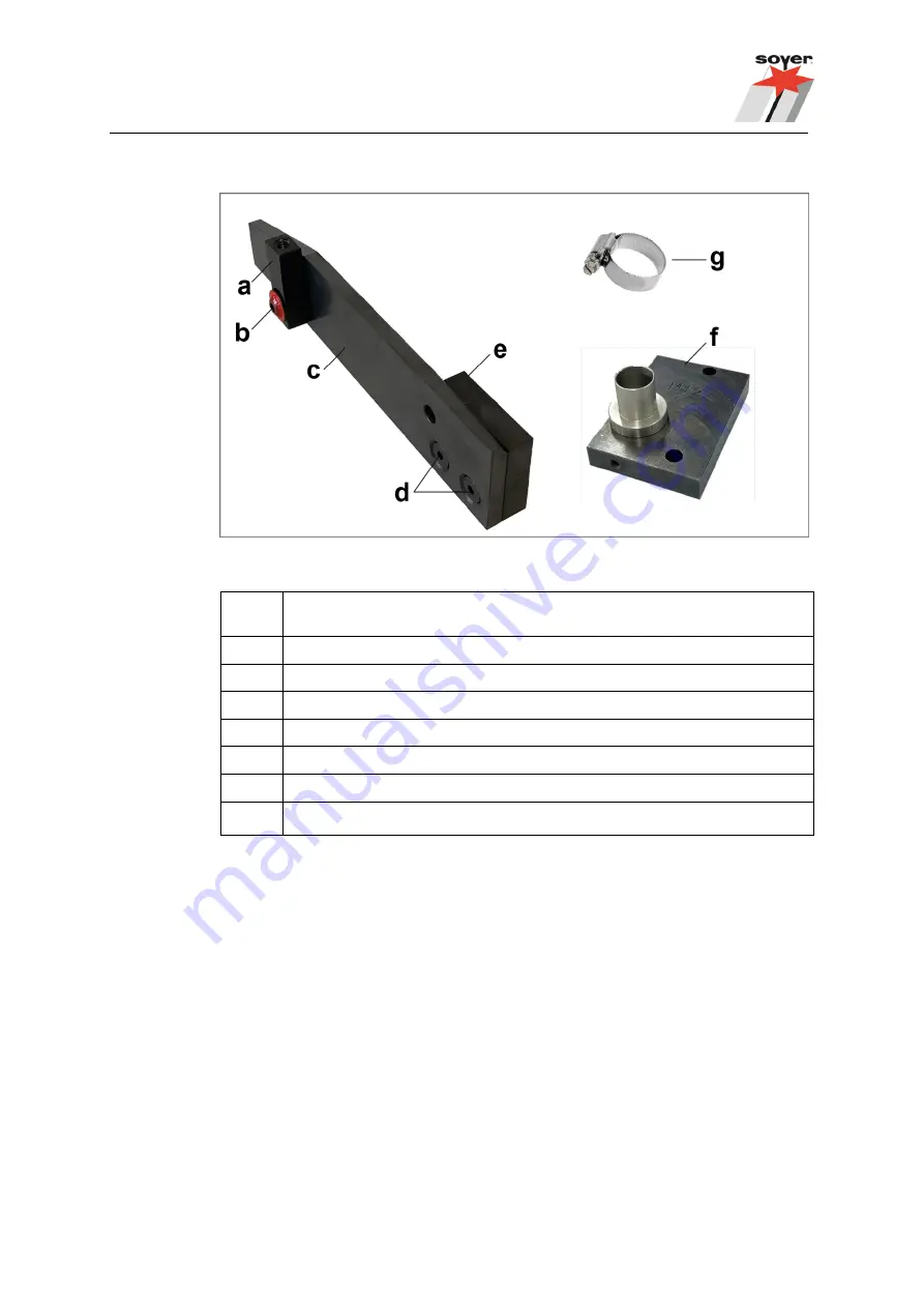
Conversion set for UVR-400 (M10, M12 and Ø 10.8) 


Figure 9: Conversion set with replaceable parts for UVR-400  


Item 

Designation 

Limit stop for fixing bracket 

Lens flange screw 

Guide rail 

Countersunk Allen screw 

Distance piece 

Hose connection 

Hose locking device 

 
All  conversion  set  parts  can  be  ordered  separately.  Please  refer  to  chapter 

“12.2 

Individual parts for the UVR-400 conversion set (M10, M12 and Ø 10.8)

” on page 62. 


Summary of Contents for UVR-300

Page 1: ...Operating Instructions UVR 300 universal feeder UVR 400 universal feeder GB English Version Read these operating instructions before starting any work Doc ID P00250 Date of issue 04 2021 www soyer com...

Page 2: ...iversal feeder UVR 300 Universal feeder UVR 400 Operating Instructions Document no P00250 04 2021 translation of the original German instructions German P00150 All information contained in this docume...

Page 3: ...0 feeder 18 6 1 1 Rear panel connections 19 6 2 Overview of the controls 21 6 2 1 Overview of the front panel 21 6 3 Display of the operating states 22 6 4 Special functions potentiometer 23 6 5 Techn...

Page 4: ...the weld studs 51 7 8 4 Readjusting the limit switch 52 8 Preparing the devices for the welding operation 53 8 1 Starting the automatic system and carrying out welding 54 8 1 1 Refilling the feeder du...

Page 5: ...revent hazards The drawings and diagrams in these operating instructions are for illustration purposes and may vary slightly from the actual equipment The manufacturer reserves the right to make techn...

Page 6: ...6 Operating instructions UVR 300 UVR 400 Heinz Soyer Bolzenschwei technik Conformity declaration Universal Feeder...

Page 7: ...ustomer specific use of the devices Information on the scope and costs of instruction and training can be obtained from Soyer GmbH 1 6 Standards and directives The following standards inter alia must...

Page 8: ...er of the situation Safety and information symbols used in this manual Imminent danger leading to severe injuries or death Potentially dangerous situation that may lead to severe injuries or death Pot...

Page 9: ...danger to life from electric current Work on electric or electronic components may only be performed by trained electrotechnical personnel in accordance with currently applicable electrotechnical reg...

Page 10: ...sconnected If protective devices have to be removed for maintenance work the device must only be switched on again when all protective devices are installed and their functionality has been checked Da...

Page 11: ...t Before working on hot parts of the device check that they have cooled down Do not hold the gun in the welding area Risk of burns from hot welding spatter Dangerous welding spatter can occur during t...

Page 12: ...d hoses from Soyer GmbH Never bridge the safety pressure switch at the cover hood do not trigger the switch if the protective hood has been removed Do not carry out a functional check when the cover h...

Page 13: ...e following instructions for protective equipment Recommended personal protection equipment Protective goggles Welding spatters and a flash of light occur during welding In order to protect your eyes...

Page 14: ...an be fed into the gun automatically using compressed air These operating instructions and the declaration of conformity only apply if the named devices are used together as described in these operati...

Page 15: ...and trained accordingly They must have read and understood these operating instructions When working with the stud welding system they must also be able to avert possible residual danger to themselve...

Page 16: ...e shutdown During storage or shutdown make sure to protect the devices against dirt and humidity Protect the stud welding system against unauthorised access by third parties 5 Disposal Local environme...

Page 17: ...n and hang in a vertical position When transporting tapped studs it cannot be ruled out that the ignition tip in the internal thread may become entangled in a preceding or subsequent tapped stud The a...

Page 18: ...tem Designation a Protective hood b Function keys of the universal feeder see 6 2 1 Overview of the front panel from page 21 c Both sides locking screws for the protective hood d Mains switch for turn...

Page 19: ...l connections Figure 2 Overview of the device back panel Item Designation a Blow air regulator b Type plate c Main air connection Observe the maximum permitted pressure d Hose package with all lines a...

Page 20: ...Overview of the transport area UVR 300 UVR 400 is similar Item Designation a Feeder bowl with welding studs b Connection piece for the stud feed hose replaceable part c Outlet rail replaceable part d...

Page 21: ...Function key ON OFF to switch the control system on off c Function key Operating mode to switch to Manual mode continuous operation Automatic mode d Function key Reload to convey a stud to the weldin...

Page 22: ...tes feeding unit Item Designation a Feeding unit ready LED lights up when line voltage is supplied b Operation LED lights up when vibration drive is in operation c Automatic LED lights up with automat...

Page 23: ...mode BMK mode preset for feeder operation J 2 is open In the light test after switching on all 6 operating displays light up and then go out again one by one BMS mode J 2 is plugged in In the light t...

Page 24: ...uds minute depending on the dimensions and feed length Feeding quantity max 6 kg Control connection Direct connection to SOYER stud welding device with feeder interface Mains connection 230 V 50 60 Hz...

Page 25: ...ds minute depending on the dimensions and feed length Feeding quantity max 8 kg Control connection Direct connection to SOYER stud welding device with feeder interface Mains connection 230 V 50 60 Hz...

Page 26: ...the device in an unventilated room There is a danger of overheating Ensure that the installation surface is flat clean and stable The installation site and workplace must comply with legal requirement...

Page 27: ...gnation a Main compressed air feed 5 7 bar b Stud feed hose c Hose package with control cable and compressed air supply from the feeder to the stud welding device c 1 Mains connection cable for the fe...

Page 28: ...rve the maximum permitted pressure Step 2 Stud feed hose Insert the stud feed hose into the connection piece a until the stop The stud feed hose and connection piece must match the stud diameter being...

Page 29: ...risk of injury from ejected welding studs Only use original stud feed hoses from Soyer GmbH Only ever use stud feed hoses which match the stud diameter Ensure correct and tight fit of the stud feed h...

Page 30: ...ug Feeder a from the feeder hose package for the controls Please note The CNC interface is not required connected Step 3 Feeder connection Supply air Connect the supply air hose a from the feeder hose...

Page 31: ...ackward black hose The universal feeder is connected with the stud welding device 6 7 Permitted devices in combination with the universal feeder Hazards due to wrong device combination Hazards for the...

Page 32: ...d head M3 M8 SK 5AKS SK 5AN No longer produced Permitted SOYER stud welding devices for automatic operation Stud welding device Note BMS 9 9V Automatic Capacitor discharge stud welding device BMS 10N...

Page 33: ...be carried out by skilled electricians in accordance with the electrotechnical regulations Make sure that no detergents get into the device Do not use aggressive detergents for cleaning the device Ma...

Page 34: ...conversion set available with the parts to be changed The parts to be converted are labelled according to the stud diameter for which they must be installed 7 1 1 Conversion set for M3 M8 preferably f...

Page 35: ...h replaceable parts for UVR 400 Item Designation a Limit stop for fixing bracket b Lens flange screw c Guide rail d Countersunk Allen screw e Distance piece f Hose connection g Hose locking device All...

Page 36: ...tud retainer Change or replace the limit stop distance plate Please also refer to chapter 7 7 Differing work steps for UVR 400 from page 44 for the different process steps regarding the following stud...

Page 37: ...et rails Adjusting the step width Step 1 Turn off the mains switch on the device disconnect the main air supply and remove the cover hood Step 2 To adjust the step width there is an adjustable plate a...

Page 38: ...ice disconnect the main air supply and remove the cover hood Step 2 Remove the hose connection a from the feeder The hose connection is fastened with a spring loaded pin Through the bore hole of the t...

Page 39: ...e correct hose connection a Ensure that the spring loaded pin clicks into place see step 2 Step 6 Insert the correct stud feed hose Ensure that the hose end is clean straight and free of burrs Lightly...

Page 40: ...ice disconnect the main air supply and remove the cover hood Step 2 Remove the hold down plate with the fastening screw a above the outlet rail Step 3 Remove the stud retainer a and rotate the desired...

Page 41: ...he compressed air lines and the compressed air nozzles Step 6 Replace the outlet rail a Take the required outlet rail a out of the conversion set Each outlet rail is labelled with the stud diameter fo...

Page 42: ...ner Step 8 Check with a stud whether this slips through the outlet rail transition a without catching If not open the tommy screw b and push the block on the transition c until there is a clean aligne...

Page 43: ...e main air supply and remove the cover hood Step 2 Remove the limit stop distance plate a by opening the tommy screw b Step 3 Remove the required limit stop distance plate from the conversion set Each...

Page 44: ...tch on the device disconnect the main air supply and remove the cover hood No limit stop distance plate a is required for the stud dimensions M10 M12 and 10 8 Remove the limit stop distance plate a an...

Page 45: ...niversal feeder Step 3 Loosen the fastening screws a and remove the connection piece b for the stud feed hose Step 4 Pull out the stud retainer a and rotate the desired diameter to the outlet rail b T...

Page 46: ...piece for the stud feed hose and rotating the stud retainer UVR 400 universal feeder Step 5 Slide the stud retainer a to the end position b until the stop Step 6 Use the hose connection required for t...

Page 47: ...f the stud retainer Ensure that there is a clean aligned transition It is helpful if a stud is already inserted in the stud retainer for this purpose This makes it easier to determine a central positi...

Page 48: ...the connection piece until the stop Step 10 Secure the stud feed hose with a hose clip a against accidental loosening Please refer to chapter 12 2 Individual parts for the UVR 400 conversion set M10...

Page 49: ...r regulator Figure 11 Blow air regulator UVR 300 UVR 400 is similar Item Designation a Manometer b Pressure regulator Pull out to make the adjustment push back in after adjusting the pressure The blow...

Page 50: ...zzles Figure 12 Blow off nozzles UVR 300 UVR 400 is similar Item Designation a Blow off nozzles b Part to be blown off example c Valve for regulating the blow off air The blow off nozzles prevent an i...

Page 51: ...sting the transport speed of the studs in the feeder bowl is located on the front panel of the device Min Minimum transport speed Max Maximum transport speed The transport speed to be adjusted depends...

Page 52: ...o hold the stud item c c Stud retainer in the transfer position to hold the stud d Stud retainer in the feed position under the stud feed hose e Stud The limit switches must be readjusted when they ar...

Page 53: ...a conversion set with the required parts Hazards due to incorrect working method Hazards for operators and third parties can arise due to an incorrect working method Ensure sufficient stability and a...

Page 54: ...understanding the operating instructions contact the manufacturer SOYER Please observe the operating instructions for the components used Carrying out welding Step 1 Before welding see chapter 2 Impor...

Page 55: ...head and device Step 8 Press either the reload button on the feeder a or e g the release button on the welding gun b until a welding stud is conveyed to the gun The function Reload can also be release...

Page 56: ...welded stud a welding stud is reloaded into the gun or head After a few seconds the system is ready to weld again LED Ready lights up 8 1 1 Refilling the feeder during operation To refill the feeder...

Page 57: ...switch The pilot lamps Network and Automatic must light up the universal feeder is only able to function when the stud welding device is switched on The control cable and or mains cable are not conne...

Page 58: ...k its function turnkey Replace if necessary The hose connection does not align with the stud retainer or the limit stop is misaligned Realign the hose connection to the stud retainer or readjust the l...

Page 59: ...ww soyer de or www soyer com English 11 Warranty conditions The warranty period for commercial or equivalent use is 12 months If repair is required we guarantee the correction of the defects at the Et...

Page 60: ...set available with the parts M3 M8 which need to be changed The parts to be converted are labelled according to the stud diameter for which they must be installed Figure 14 Conversion set UVR 300 exc...

Page 61: ...rsion set UVR 300 exchange parts 2 Individual parts in the feeder conversion set Item Description Dimension Item no a Limit stop for fixing bracket F05335 b Lens flange screw M5 x12 mm M03870 c Guide...

Page 62: ...ts Conversion parts UVR 400 M10 M12 and 10 8 Item Description Dimension Item no a Limit stop for fixing bracket F05335 b Lens flange screw M5 x12 mm M03870 c Guide rail F05572 d Countersunk Allen scre...

Page 63: ...Operating instructions UVR 300 UVR 400 Heinz Soyer Bolzenschwei technik 63...

Page 64: ...Heinz Soyer Bolzenschwei technik GmbH Inninger Stra e 14 82237 W rthsee Tel 0049 8153 885 0 E Mail info soyer de www soyer de...

Reviews: