Whisper 500 Battery Charging Manual
Document #0023 Rev C
SOUTHWEST WINDPOWER
April 2006
5. Whisper Controller Printed Circuit Board
Introduction
The Whisper Controller Printed Circuit Board is equipped with six switches that are used to set certain
operating system parameters. The default switch settings are suitable for the majority of installations and
should not be changed with the exception of two switches that MUST be changed to alter the system volt-
age.
Instructions for changing the system voltage are given below.
The printed circuit board is also equipped with a “Reset” switch that is used to reset the microprocessor. De-
pressing the switch has the same effect as disconnecting a battery cable from the Whisper Controller.
Note that if voltage regulation points are set using the Optional Display they will be lost if the Reset
Switch is depressed or a battery cable is disconnected. In this case the controller will revert to the
potentiometer set points. Refer to sections on Reset Switch, Adjusting the System Voltage and Op-
tional Display for additional information.
Printed Circuit Board Switch Settings
Switches 1 and 2, System Voltage
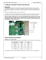
Select the correct system voltage by setting the position of Switches 1 and 2 according to the following table.
After changing the system voltage depress the Reset switch to “read and save” the new voltage setting.
Default Switch Settings
for 24 Volt Operation
1. OFF
2. ON
3. ON
4. OFF
5. OFF
6. OFF
Potentiometer
Reset Switch
System Voltage
Switch 1
Switch 2
12 Volt
ON
ON
24 Volt
OFF
ON
36 Volt
ON
OFF
48 Volt
OFF
OFF
22

