Whisper 500 Battery Charging Manual
Document #0023 Rev C
SOUTHWEST WINDPOWER
April 2006
LCD Display Operation
Operational Overview
The LCD Display adds a tremendous set of features to your wind generator system. Controller measure-
ments can be monitored and operational parameters can be adjusted. Take the time to learn about your
Whisper Controller Display to take advantage of its many features.
LED Display
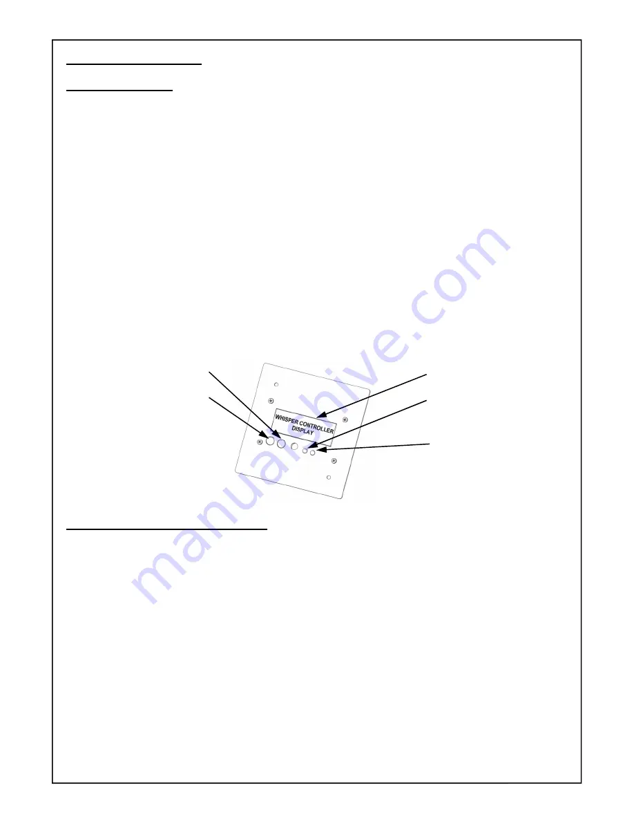
Like the Controller itself, the LCD display has a Red and a Green LED and they function in exactly the same
way.
Refer to the Section 7 for detailed information. Due to controller lag time, there may be a delay in updating
one set of LEDs. Therefore, it is recommended that if the Display is mounted in the lid of the Controller, that
the Display be plugged into the Controller board jack in the lower right corner of the Controller board. This will
automatically disable the Display’s LEDs. The Controller board jack closest to the Diversion switch should be
used for a remotely mounted display.
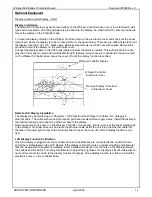
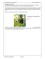
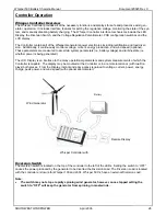
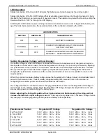
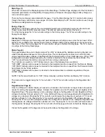
LCD Contrast Potentiometer
The contrast potentiometer can be accessed through the cover of the Display unit via a hole situated between
the buttons and the LEDs. The pot is optimized at the factory for room temperature operation; however, de-
viations from room temperature can cause the LCD to appear too dark or too light. Carefully insert a screw-
driver through the display lid and turn the potentiometer counter-clockwise to increase the darkness of the
LCD.
Functions Available Through the Display
Functions available through the display are accessed using two Menu Function Buttons—the “A” button and
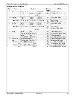
“B” button. See the figure above. Depressing one of the buttons selects another “Menu Page” according to
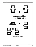
the Page Structure Chart on Page 21. For example depressing the “A” Button from the “Main” Page causes
selection of the “Energy Page”. Depressing the “A” Button a second time causes selection of the “History
Page”.
Refer to the Menu Chart and Menu Navigation “Map” on the following pages to see all the Menu Pages and
information available for display. The following sections present detailed information about the information
and functions available on each page.
Note that each of the menu pages in this is an access point for various controller and display settings. The
“A” and “B” buttons scroll between the menu pages, or change parameters on the menu, or sub-pages. The
Reference Numbers in the following paragraph headings refer to Ref # column in the following chart.
LCD Display Screen
Green LED
Red LED
LCD Contrast Adjustment
“A” Menu Function Button
“B” Menu Function Button
28

