www.soundskulptor.com
Document revision 1.3 – Last modification : 28/02/20
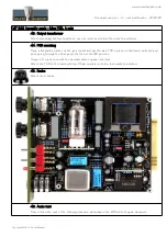
MP 566 Assembly guide – Main PCB, A side
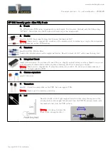
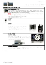
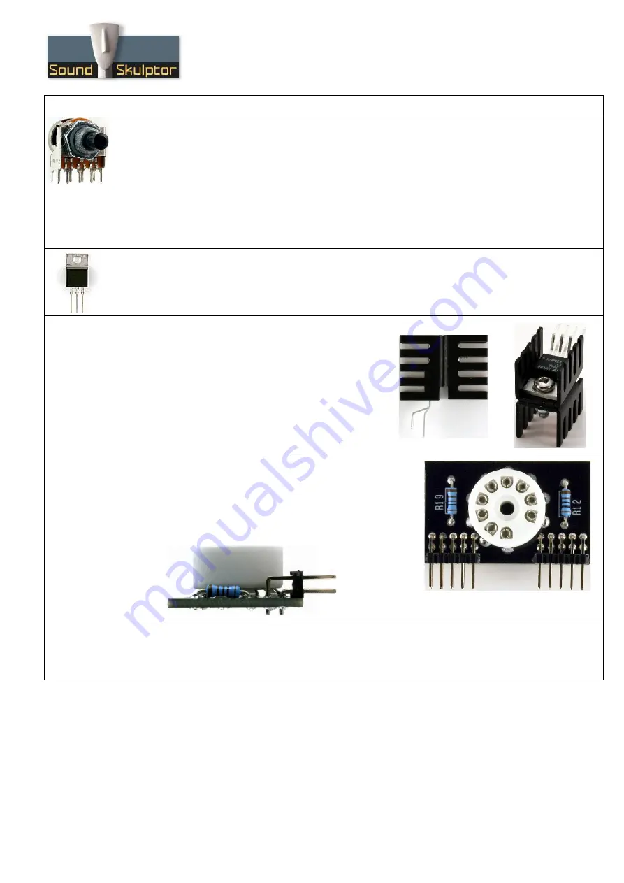
28. Potentiometers P1 & P2
Place the bracket on the potentiometer bushing, and attach it with the lock washer and nut. Tighten.
Insert potentiometer and bracket into the PCB holes. Solder the central potentiometer pin. Now check
that the potentiometer shaft is perfectly parallel to the board.
Warning
: Do not only rely on the bracket being flat on the PCB, it sometimes need little visually made
adjustments to get a perfect position.
Once the position is correct, solder the other pins.
Finish tightening the nut, without excess.
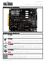
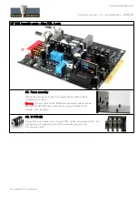
29. U7
Add U7.
30. U2
Mount two heatsinks back to back on U2, with a 10mm
screw and a self locking nut.
Insert U2 on the PCB and solder one pin. Check the
verticality then solder the other pins.
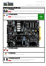
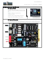
31. Tube PCB (A)
Solder R12 and R19.
Solder the two 2 x 5 pins 90° pin headers. Solder one pin first,
check the header sits flat on the PCB, then solder the other pins.
Solder the tube socket and cut the pins flush.
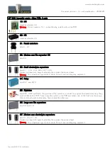
32. Tube PCB assembly
Insert the tube holder PCB into the main PCB. Solder one pin first, check the tube PCB is perfectly
perpendicular to the main PCB, then solder the other pins.
Copyright ©2015 SoundSkulptor


