www.soundskulptor.com
Document revision 1.3 – Last modification : 28/02/20
MP 566 Assembly guide – Main PCB, A side
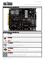
14. Pin header
Solder the 6 pins header CN1. Solder one pin first, check verticality, then solder the other pins.
Warning
: Make sure the pin are perfectly vertical. This is important for a good position of the DI jack.
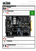
15. Ceramic capacitors
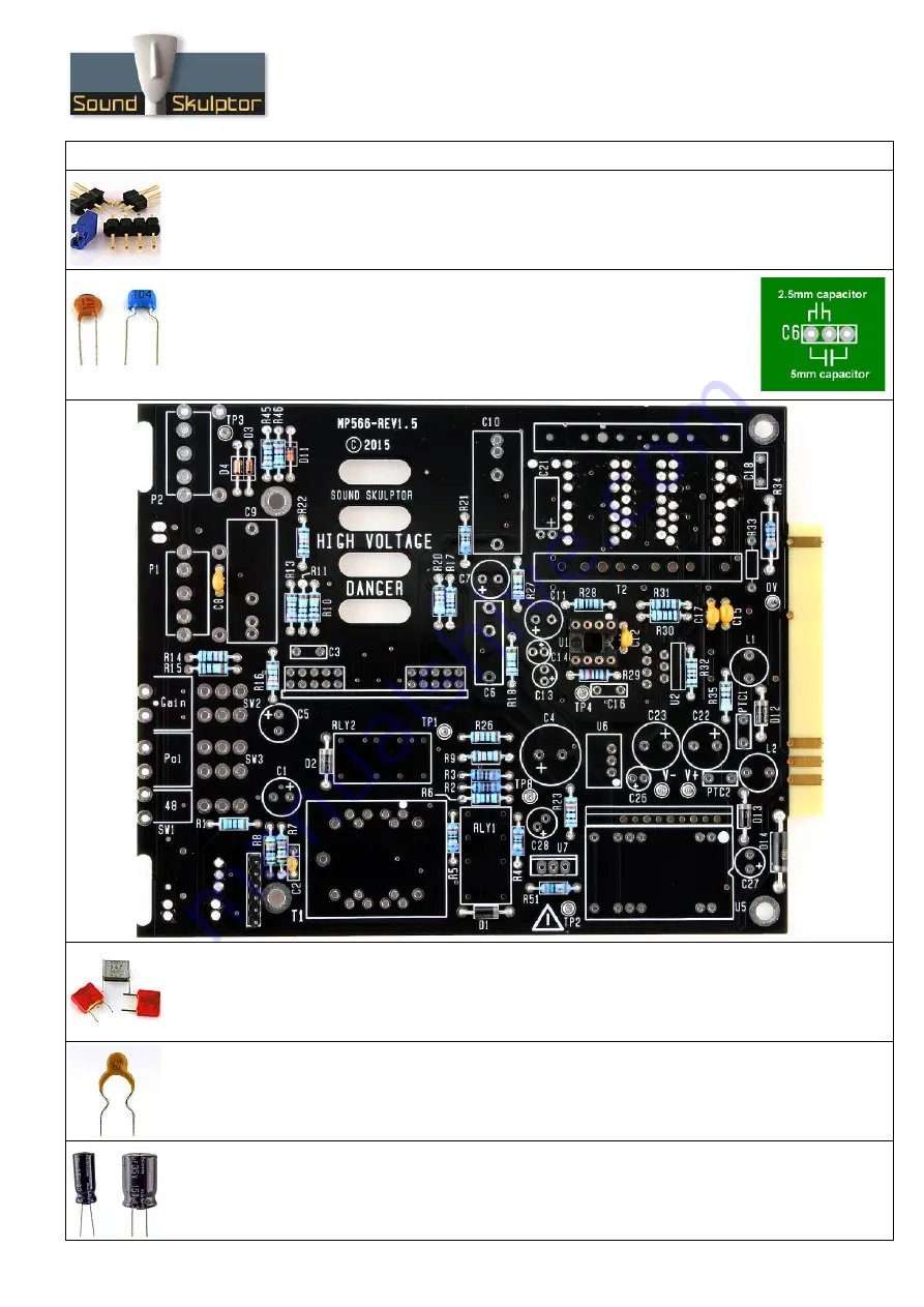
Add C2, C8, C12, C15, C17.
Warning
: Some capacitors have provision for 2 sizes. Small size capacitors must be
inserted in the correct holes as shown in the picture.
16. Small film capacitors
Add C3, C16.
17. Polymer fuses
Solder the 2 resettable fuses PTC1 and PTC2.
18. Electrolytic capacitor C21
Insert the electrolytic capacitor C21 and lay it down flat on the PCB. Solder.
Warning
: The +lead must go into the +hole. Do not reverse.
Copyright ©2015 SoundSkulptor


