www.soundskulptor.com
Document revision 1.3 – Last modification : 28/02/20
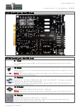
MP 566 Assembly guide – Main PCB, B side
2. B side
The MP566 main PCB carries components on both sides. The A side is the side with the title writing
“MP566”. We will start by the B side which holds only a few components.
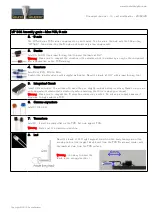
3. Diodes
Add D5 to D9. Use a lead forming tool to bend the leads at 0.4”.
Warning
: Make sure to respect the direction of the diodes which is marked by a ring on the component
and a double line on the PCB marking.
4. Resistors
Add R24, R25, R36 to R44.
Control the resistor values with a digital multimeter. Bend the leads at 0.4” with a lead forming tool.
5. Integrated Circuit
Insert U3 and solder. You will need to bend the pins slightly inwards before inserting. Make sure you are
not charged with electrostatic electricity before handling the IC (or remove your shoes).
Warning
: Make sure to respect the IC direction, marked by a notch. Do not use a socket because it
would be to high under the PCB.
6. Ceramic capacitors
Add C19 & C20.
7. Transistors
Add Q1. It must be placed flat on the PCB, flat side against PCB.
Warning
: Watch out the transistor direction.
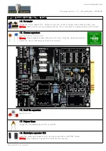
8. Led
Bend the leads of D10 right angle at 6mm from the body taking care of the
anode position (the longest lead).Insert from the PCB B side and solder with
the leads at 2mm from the PCB surface.
Warning
: it is easy to bend the
leads in the wrong direction !
Copyright ©2015 SoundSkulptor


