www.soundskulptor.com
Document revision 1.3 – Last modification : 28/02/20
MP 566 Assembly guide – Main PCB, A side
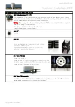
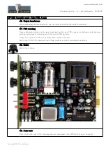
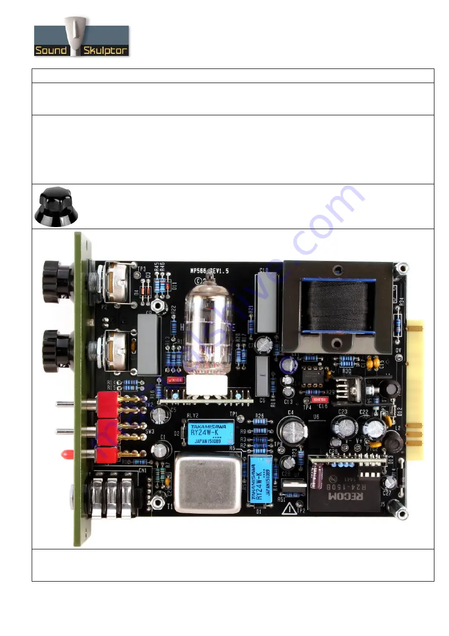
43. Output transformer
After succeeding the functional test, you can insert and solder the output transformer.
44. PCB mounting
Place a flat plastic washer on the jack socket and put the main PCB in place on the frame, switches and
pots going through the front panel. Watch out the LED position.
Screw in the jack nose with the bevelled plastic spacer inserted.
Attach the PCB to the frame with four 25mm spacers, with four lock washers inserted.
45. Knobs
Attach the 2 knobs.
46. Audio test
Please follow the rest of the testing procedure described in the MP566 test guide document.
Copyright ©2015 SoundSkulptor


